
1. Introduction
The ANENG AN8002 is an auto-ranging digital multimeter designed for precise electrical measurements. It utilizes a double-integral style A/D transform for its core measurement function, ensuring stable performance and high reliability. This device is battery-powered and features overload protection, a large LCD display for clear readings, and automatic polarity recognition. It is an ideal tool for electronics enthusiasts, technicians, and general household use.
Key features include:
- Auto Range and True RMS measurement capabilities.
- Measures AC/DC Voltage, AC/DC Current, Resistance, Capacitance, Frequency, and Temperature.
- Diode and Continuity testing.
- High voltage protection up to 550V for resistance, capacitance, and frequency modes.
- Large display with 6000 counts.
- Sampling rate of approximately 3 times per second.
- Backlight display and Data Hold function.
- Low voltage display and Automatic Shutdown feature.
2. Safety Information
Please read and understand all safety information before operating this multimeter. Failure to follow these instructions may result in electric shock, fire, or damage to the meter.
- Always ensure the test leads are correctly inserted into the appropriate input jacks for the measurement being performed.
- Do not apply voltage or current that exceeds the maximum specified limits for the selected range.
- Exercise extreme caution when working with voltages above 30V AC RMS, 42V peak, or 60V DC. These voltages pose a shock hazard.
- Before measuring current, ensure the circuit is de-energized and the meter is connected in series with the load.
- Before measuring resistance, capacitance, or diode, ensure the circuit is de-energized and all capacitors are discharged.
- Do not use the meter if it appears damaged or if the test leads are damaged.
- Replace batteries immediately when the low battery indicator appears to ensure accurate readings.
- Do not operate the meter in explosive gas, vapor, or dusty environments.
- Always use the correct function and range for measurements.
3. Product Overview
The ANENG AN8002 Digital Multimeter features a compact design with a clear LCD display and intuitive controls.

Figure 3.1: Front view of the ANENG AN8002 Digital Multimeter, showing the display, rotary switch, and input jacks.

Figure 3.2: The ANENG AN8002 Digital Multimeter with its integrated kickstand extended for convenient viewing.
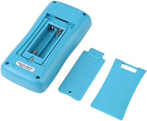
Figure 3.3: Rear view of the multimeter, showing the open battery compartment for AAA batteries.
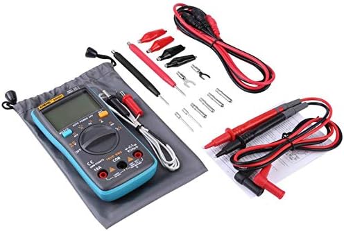
Figure 3.4: The ANENG AN8002 Multimeter displayed with its full set of accessories, including test leads, alligator clips, and temperature probe.
3.1. Components
- LCD Display: Shows measurement readings, units, and function indicators.
- Rotary Switch: Used to select measurement functions (Voltage, Current, Resistance, etc.).
- Function Buttons: Include HOLD/Backlight, AUTO POWER OFF/Hz, %/Ω, SEL (Select).
- Input Jacks:
- COM Jack: Common input for all measurements (negative connection).
- VΩHz-+mA Jack: Input for voltage, resistance, frequency, capacitance, diode, continuity, and milliampere current measurements.
- 10A Jack: Input for high current measurements (up to 10A).
4. Setup
4.1. Battery Installation
The ANENG AN8002 Multimeter is powered by two AAA batteries (not included).
- Ensure the multimeter is turned off.
- Locate the battery compartment cover on the back of the unit (refer to Figure 3.3).
- Use a screwdriver to remove the screw securing the battery cover.
- Carefully remove the cover.
- Insert two AAA batteries, observing the correct polarity (+ and -) as indicated inside the compartment.
- Replace the battery cover and secure it with the screw.
4.2. Connecting Test Leads
Always connect the test leads correctly for the desired measurement.

Figure 4.1: The multimeter with red and black test leads properly connected to the input jacks.
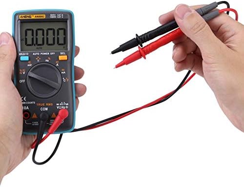
Figure 4.2: A user holding the test leads, ready to perform a measurement.
- Insert the black test lead into the COM (Common) jack.
- For most measurements (Voltage, Resistance, Capacitance, Frequency, Diode, Continuity, mA current), insert the red test lead into the VΩHz-+mA jack.
- For high current measurements (up to 10A), insert the red test lead into the 10A jack.
5. Operating Instructions
5.1. Power On/Off
Turn the rotary switch from the "OFF" position to any desired measurement function to power on the multimeter. To power off, turn the rotary switch back to the "OFF" position.
5.2. Automatic Shutdown
The multimeter features an automatic shutdown function to conserve battery life. If no operation is performed for a certain period, the meter will automatically power off. Press any button or turn the rotary switch to reactivate it.
5.3. Data Hold (HOLD)
Press the "HOLD" button to freeze the current reading on the display. Press it again to release the hold function.
5.4. Backlight
Press and hold the "HOLD" button to turn the display backlight on or off.
5.5. DC Voltage Measurement (V–)
- Set the rotary switch to the "V–" position.
- Connect the black test lead to the COM jack and the red test lead to the VΩHz-+mA jack.
- Connect the test probes across the DC voltage source to be measured.
- Read the voltage value on the display.
5.6. AC Voltage Measurement (V∼)
- Set the rotary switch to the "V∼" position.
- Connect the black test lead to the COM jack and the red test lead to the VΩHz-+mA jack.
- Connect the test probes across the AC voltage source to be measured.
- Read the voltage value on the display.
5.7. DC Current Measurement (A–, mA–)
- Set the rotary switch to the "A–" or "mA–" position. Use the "SEL" button to switch between DC and AC if necessary.
- For currents up to 600mA, connect the red test lead to the VΩHz-+mA jack. For currents up to 10A, connect the red test lead to the 10A jack. The black test lead always connects to COM.
- De-energize the circuit and open the circuit where the current is to be measured.
- Connect the multimeter in series with the circuit.
- Re-energize the circuit and read the current value on the display.
5.8. AC Current Measurement (A∼, mA∼)
- Set the rotary switch to the "A∼" or "mA∼" position. Use the "SEL" button to switch between DC and AC if necessary.
- For currents up to 600mA, connect the red test lead to the VΩHz-+mA jack. For currents up to 10A, connect the red test lead to the 10A jack. The black test lead always connects to COM.
- De-energize the circuit and open the circuit where the current is to be measured.
- Connect the multimeter in series with the circuit.
- Re-energize the circuit and read the current value on the display.
5.9. Resistance Measurement (Ω)
- Set the rotary switch to the "Ω" position.
- Connect the black test lead to the COM jack and the red test lead to the VΩHz-+mA jack.
- Ensure the circuit is de-energized and all capacitors are discharged.
- Connect the test probes across the component to be measured.
- Read the resistance value on the display.
5.10. Capacitance Measurement (µF)
- Set the rotary switch to the "µF" position.
- Connect the black test lead to the COM jack and the red test lead to the VΩHz-+mA jack.
- Ensure the capacitor is fully discharged before connecting the test probes.
- Connect the test probes across the capacitor.
- Read the capacitance value on the display.
5.11. Frequency Measurement (Hz) and Duty Cycle (%)
- Set the rotary switch to the "Hz" position.
- Connect the black test lead to the COM jack and the red test lead to the VΩHz-+mA jack.
- Connect the test probes across the signal source.
- Read the frequency value on the display. Press the "%" button to view the duty cycle.
5.12. Temperature Measurement (°C/°F)
- Set the rotary switch to the "°C/°F" position.
- Connect the temperature probe (thermocouple) to the VΩHz-+mA and COM jacks, observing polarity.
- Place the probe tip on or near the object whose temperature is to be measured.
- Read the temperature value on the display. Press the "SEL" button to switch between Celsius and Fahrenheit.
5.13. Diode Test (→|–)
- Set the rotary switch to the "→|–" position.
- Connect the black test lead to the COM jack and the red test lead to the VΩHz-+mA jack.
- Ensure the diode is disconnected from the circuit.
- Connect the red probe to the anode and the black probe to the cathode of the diode. A forward voltage drop will be displayed.
- Reverse the probes. The display should show "OL" (Over Load) for a good diode.
5.14. Continuity Test (♫)
- Set the rotary switch to the "♫" position.
- Connect the black test lead to the COM jack and the red test lead to the VΩHz-+mA jack.
- Ensure the circuit is de-energized.
- Connect the test probes across the circuit or component.
- If the resistance is below approximately 50Ω, the buzzer will sound, indicating continuity.
6. Maintenance
6.1. Cleaning
Wipe the case with a damp cloth and mild detergent. Do not use abrasives or solvents. Ensure the meter is completely dry before use.
6.2. Battery Replacement
When the low battery indicator appears on the display, replace the batteries as described in Section 4.1. Prompt battery replacement ensures accurate measurements.
6.3. Fuse Replacement
If the current measurement function fails, the fuse may need replacement. Refer to the markings on the device for fuse specifications (e.g., FUSED 10A MAX, FUSED 600mA MAX). Fuse replacement should only be performed by qualified personnel.
7. Troubleshooting
- Display shows "OL": This indicates an over-range condition (measurement exceeds the meter's maximum capacity for the selected range) or an open circuit. Check your connections and the range setting.
- No display or dim display: Check battery installation and battery level. Replace batteries if necessary.
- Inaccurate readings: Ensure test leads are properly connected, batteries are fresh, and the correct function/range is selected. External interference can also affect readings.
- Current measurement not working: Check the fuse. If blown, replace it with a fuse of the correct rating.
8. Specifications
| Measurement | Range | Resolution |
|---|---|---|
| DC Voltage | Up to 1000V | 0.1mV |
| AC Voltage | Up to 750V | 0.1mV |
| DC Current | Up to 10A | 0.1µA |
| AC Current | Up to 10A | 0.1µA |
| Resistance | 0.1Ω to 60MΩ | 0.1Ω |
| Capacitance | Up to 6000µF | 10pF |
| Frequency | Up to 10MHz | 1Hz |
| Temperature | -20°C to 1000°C (-4°F to 1832°F) | 1°C/°F |
| Duty Cycle | 1% to 99% | N/A |
General Specifications
- Measurement Mode: Double-integral style A/D transform
- Sample Rate: 3 times per second
- Over Range Indication: OL
- Power: 2 x AAA batteries (Not included)
- Working Environment: 0-40°C, relative humidity: <80%
- Product Size: Approx. 130 x 65 x 30mm (5.11 x 2.55 x 1.18 inches)
- Net Weight: Approx. 170g
- Display: 6000 Counts
- Color: Blue (device casing)
- Material: Silicone / Metal
9. Warranty and Support
For warranty information or technical support, please refer to the documentation provided with your purchase or contact the seller directly. Keep your purchase receipt as proof of purchase.


