1. Introduction
The BSIDE ADM92CL is a compact, True RMS digital multimeter designed for accurate measurement of various electrical parameters. It features an auto-ranging function, a color display, and capabilities for measuring AC/DC voltage, AC/DC current, resistance, capacitance, frequency, temperature, diode, continuity, NCV (Non-Contact Voltage), and live wire detection. This manual provides essential information for safe and effective operation of the device.
2. Safety Information
Always adhere to basic safety precautions when using this multimeter to prevent personal injury or damage to the device or equipment under test. Read all safety information before use.
- Do not exceed the maximum input values specified for each range.
- Exercise extreme caution when working with voltages above 36V DC or 25V AC RMS. These voltages pose a shock hazard.
- Ensure the test leads are in good condition, without any damage to the insulation.
- Always disconnect power to the circuit and discharge all high-voltage capacitors before performing resistance, continuity, diode, or capacitance measurements.
- Do not operate the meter if it appears damaged or if the battery cover is not properly closed.
- Use the correct function and range for measurements.
- Replace batteries when the low battery indicator appears to ensure accurate readings.
3. Package Contents
Verify that all items are present in the package:
- BSIDE ADM92CL Digital Multimeter
- Test Leads (Red and Black)
- K-type Thermocouple (Temperature Probe)
- Storage Pouch
- User Manual

Contents of the BSIDE ADM92CL Digital Multimeter package, including the device, test leads, temperature probe, and user manual.
4. Product Overview and Parts Identification
Familiarize yourself with the components and controls of the BSIDE ADM92CL Digital Multimeter.

Labeled diagram of the BSIDE ADM92CL Digital Multimeter's components and controls.
- Input Terminals: Connect test leads for measurements.
- COM Terminal: Common (negative) input for all measurements.
- Rotary Switch: Selects the primary measurement function (e.g., Voltage, Resistance, Current).
- Display: Color LCD screen showing measurement readings, units, and indicators.
- HOLD / ☀ Button: Press to hold the current reading on the display. Long press to activate/deactivate backlight.
- SEL Button: Selects sub-functions within a rotary switch position (e.g., AC/DC voltage, Diode/Continuity).
- Hz Button: Activates frequency measurement mode.
- V~Alert Button: Activates Non-Contact Voltage (NCV) detection.
- V~Alert Sensor Area: Detects AC voltage without direct contact.
- Slot: For attaching accessories or for convenient storage.

Detailed view of the BSIDE ADM92CL Multimeter's color LCD display, input ports, side slot, and back clip.
5. Setup
5.1 Battery Installation
The multimeter requires batteries for operation. To install or replace batteries:
- Ensure the multimeter is turned OFF.
- Locate the battery compartment on the back of the device.
- Open the battery compartment cover.
- Insert the batteries, observing the correct polarity (+/-).
- Close the battery compartment cover securely.
5.2 Connecting Test Leads
For most measurements, connect the test leads as follows:
- Insert the black test lead into the COM (Common) input jack.
- Insert the red test lead into the INPUT jack.
6. Operating Instructions
This section details how to use the multimeter for various measurements.
6.1 General Operation
- Turn the rotary switch to the desired measurement function.
- If a function has multiple modes (e.g., AC/DC voltage), press the SEL button to cycle through them.
- Connect the test leads to the circuit or component under test.
- Read the measurement value on the display.
6.2 Voltage Measurement (AC/DC)
- Set the rotary switch to the “V” position.
- Press SEL to select AC (“ACV”) or DC (“DCV”) voltage.
- Connect the test leads in parallel to the circuit or component.
6.3 Current Measurement (AC/DC)
- Set the rotary switch to the “mA/A” position.
- Press SEL to select AC (“ACA”) or DC (“DCA”) current.
- Connect the multimeter in series with the circuit. Ensure the circuit is open before connecting the meter.
6.4 Resistance Measurement
- Set the rotary switch to the “Ω” position.
- Connect the test leads across the component. Ensure the component is de-energized.
6.5 Continuity Test
- Set the rotary switch to the “Ω” position.
- Press SEL until the continuity symbol (“♫”) appears.
- Connect the test leads across the circuit or component. A continuous beep indicates continuity.
6.6 Diode Test
- Set the rotary switch to the “Ω” position.
- Press SEL until the diode symbol (“→|”) appears.
- Connect the red lead to the anode and the black lead to the cathode of the diode.
6.7 Capacitance Measurement
- Set the rotary switch to the “Cap” position.
- Connect the test leads across the capacitor. Ensure the capacitor is discharged before testing.
6.8 Temperature Measurement
- Set the rotary switch to the “Temp” position.
- Connect the K-type thermocouple to the input jacks, observing polarity.
- Place the thermocouple tip on or in the object whose temperature is to be measured.
BSIDE ADM92CL Digital Multimeter measuring temperature with a K-type thermocouple.
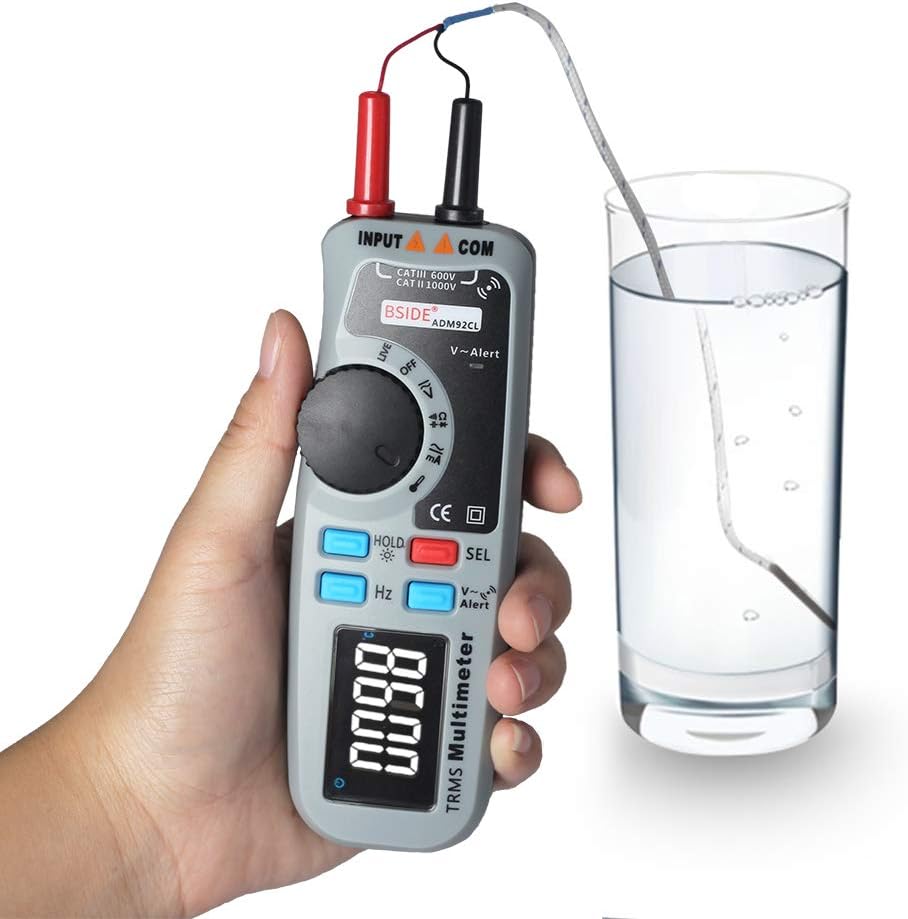
6.9 NCV (Non-Contact Voltage) Detection
- Press the V~Alert button.
- Move the top end of the multimeter (V~Alert sensor area) close to an AC voltage source. The meter will beep and the display will indicate the presence of AC voltage.
6.10 Live Wire Detection
- Set the rotary switch to the “Live” position.
- Insert the red test lead into the live wire socket. The display will indicate if the wire is live.
6.11 Frequency (Hz) Measurement
- Set the rotary switch to a voltage or current function.
- Press the Hz button. The meter will display the frequency of the measured signal.
6.12 Data Hold and Backlight
- Data Hold: Press the HOLD button briefly to freeze the current reading on the display. Press again to release.
- Backlight: Long press the HOLD button to turn the display backlight ON or OFF.
7. Maintenance
7.1 Cleaning
Wipe the case with a damp cloth and mild detergent. Do not use abrasives or solvents. Keep the input terminals free from dirt and moisture.
7.2 Battery Replacement
When the low battery indicator appears on the display, replace the batteries immediately to ensure accurate measurements. Refer to section 5.1 for battery installation instructions.
7.3 Storage
If the meter is not used for an extended period, remove the batteries to prevent leakage and damage. Store the device in a cool, dry place, away from direct sunlight and extreme temperatures.
8. Troubleshooting
If the multimeter does not function correctly, refer to the following common issues and solutions:
| Problem | Possible Cause | Solution |
|---|---|---|
| No display or dim display | Dead or low batteries | Replace batteries. |
| Incorrect readings | Incorrect function/range selected; poor test lead connection; damaged test leads. | Verify function/range; ensure secure connections; inspect and replace test leads if damaged. |
| Meter does not respond | Internal fault; battery issue. | Remove and reinsert batteries. If problem persists, contact support. |
| Continuity test always beeps | Test leads shorted. | Separate test leads; check for internal short in leads. |
9. Specifications
Technical specifications for the BSIDE ADM92CL Digital Multimeter:
- Measurement Type: Multimeter
- Display: Color LCD, 6000 Counts
- True RMS: Yes
- Auto Range: Yes
- Power Source: Battery Powered
- Style: Digital
- Manufacturer: China
- Item Model Number: BSIDE ADM92CL
- UPC: 630282713741
10. Warranty and Support
For warranty information or technical support, please refer to the documentation included with your purchase or contact the retailer. Keep your purchase receipt as proof of purchase.


