
1. Product Overview
The WINGONEER ATtiny Development Programmer Board is designed for convenient and high-speed programming of ATtiny series microcontrollers. This plug-in board supports a range of ATtiny chips, including ATtiny13A, ATtiny25, ATtiny45, and ATtiny85. It features a Micro USB connector for power and data communication, making it suitable for various embedded development projects.
Each package includes 5 development programmer boards, each measuring approximately 2.5 x 1.7 cm. The board integrates a DIP-8 socket for easy insertion and removal of the target ATtiny microcontroller.
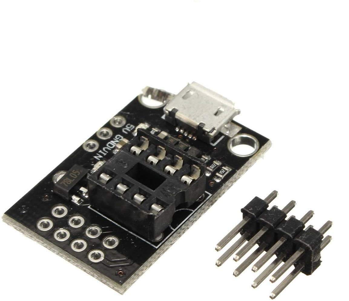
Figure 1: Top view of the WINGONEER ATtiny Development Programmer Board, showing the Micro USB port, DIP socket, and various components.
2. Setup Instructions
- Prepare the ATtiny Microcontroller: Ensure your ATtiny13A, ATtiny25, ATtiny45, or ATtiny85 chip is ready for programming. Carefully align the chip with the DIP-8 socket on the programmer board, ensuring the notch on the chip matches the orientation of the socket. Gently insert the chip into the socket.
- Connect to Computer: Use a standard Micro USB cable (not included) to connect the programmer board to a USB port on your computer. The board will draw power from the USB connection.
- Install Drivers (if necessary): Your operating system should typically recognize the device automatically. If not, you may need to install specific USB-to-serial drivers, depending on the underlying chip used for USB communication on the programmer board. Refer to your operating system's device manager for unrecognized devices.
- Configure Development Environment: Set up your preferred Integrated Development Environment (IDE), such as the Arduino IDE, with the necessary ATtiny core support. This typically involves adding a board manager URL and installing the ATtiny boards package.
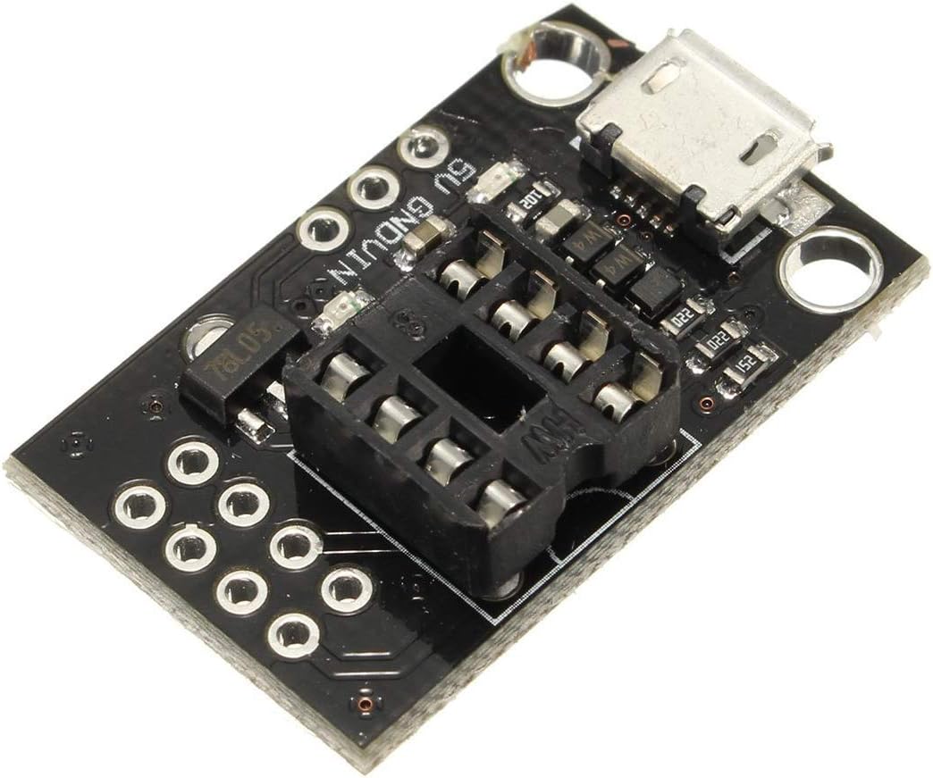
Figure 2: Angled view of the programmer board, highlighting the Micro USB port and the DIP socket for chip insertion.
3. Operating Instructions
- Select Board and Programmer: In your IDE (e.g., Arduino IDE), go to Tools > Board and select the appropriate ATtiny board (e.g., "ATtiny25/45/85" or "ATtiny13"). Then, go to Tools > Programmer and select the programmer that corresponds to your setup (e.g., "USBasp" or "Arduino as ISP" if you are using a direct programmer).
- Burn Bootloader (if required): For some ATtiny setups, you might need to burn a bootloader once. Go to Tools > Burn Bootloader. This step is often not strictly necessary for direct programming with a dedicated programmer but can be useful for initial setup or if you intend to use the chip with a bootloader later.
- Write and Upload Code: Write your program (sketch) in the IDE. Once your code is ready, click the Upload button (or Sketch > Upload Using Programmer if you selected a specific programmer). The IDE will compile your code and upload it to the ATtiny chip on the programmer board.
- Verify Operation: After successful upload, disconnect the programmer board from your computer. Remove the ATtiny chip and integrate it into your target circuit to verify its functionality.
4. Maintenance
- Keep the programmer board clean and dry. Avoid exposure to moisture, dust, and extreme temperatures.
- Handle the board and ATtiny chips with care to prevent physical damage to components or pins.
- When not in use, store the boards in an anti-static bag or container to protect them from electrostatic discharge (ESD).
- Regularly check the Micro USB port for debris or damage to ensure reliable connection.
5. Troubleshooting
- Board Not Recognized by Computer:
- Ensure the Micro USB cable is fully inserted and functional. Try a different cable or USB port.
- Check your computer's Device Manager (Windows) or System Information (macOS/Linux) for any unrecognized devices or driver issues. Install necessary USB-to-serial drivers if prompted or if the device appears with an error.
- Restart your computer.
- Programming Errors / Chip Not Responding:
- Verify the ATtiny chip is correctly seated in the DIP socket, with the correct orientation.
- Ensure you have selected the correct board and programmer in your IDE.
- Check your wiring if you are using external components or an external power supply.
- Confirm the ATtiny chip itself is functional. Try with a different chip if available.
- Ensure your IDE and ATtiny core are up to date.
- Power Issues:
- Ensure your USB port provides sufficient power. Avoid unpowered USB hubs.
- If using an external power source, ensure it provides the correct voltage (typically 5V for this board).
6. Specifications
| Brand | WINGONEER |
| Model Number | 1828 |
| Supported Microcontrollers | ATtiny13A, ATtiny25, ATtiny45, ATtiny85 (DIP-8 package) |
| Connectivity | Micro USB |
| Power Source | USB Bus Power (5V) |
| Dimensions | Approx. 2.5 x 1.7 cm |
| CPU Manufacturer (for target chips) | Atmel |
| GTIN / UPC | 753387767690 |
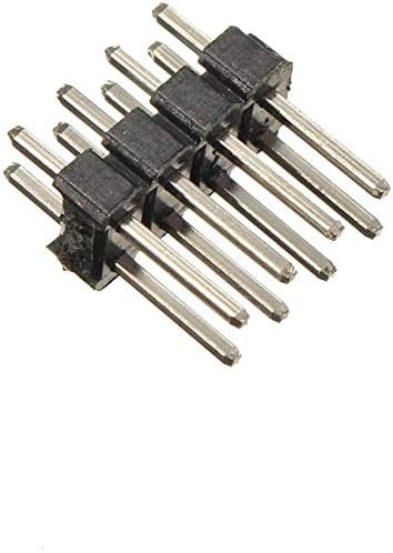
Figure 3: Example of pin headers that may be used with the development board for external connections.
7. Warranty and Support
Specific warranty information for this product is not provided in the available data. For support, technical assistance, or warranty inquiries, please contact your retailer or the manufacturer, WINGONEER, directly through their official channels or the platform where the product was purchased.
Always refer to the product packaging or the seller's information for the most accurate and up-to-date warranty and support details.