
1. Introduction
This manual provides detailed instructions for the installation, operation, and maintenance of the EPEVER 100A MPPT Solar Charge Controller, Tracer-AN Series. This high-power charge controller is designed for solar systems and is compatible with 12V, 24V, 36V, and 48V lead-acid and lithium batteries. It features advanced MPPT control algorithms and multiphase synchronous rectification technology (MSRT) for high efficiency and reliability.

Figure 1.1: Front view of the EPEVER Tracer-AN Series MPPT Solar Charge Controller. This image shows the compact design with an LCD display and control buttons.
1.1 Key Features
- Advanced MPPT technology with ultra-fast tracking speed (no less than 99.5% tracking efficiency).
- High DC/DC transfer efficiency (up to 98.6%) and full load efficiency (up to 98%).
- Automatic identification of 12V/24V/36V/48V DC system voltage.
- Compatibility with various battery types: Sealed, Gel, Flooded, and Lithium.
- Maximum input current of 100A.
- Maximum PV input power: 1250W/12V, 2500W/24V, 3750W/36V, 5000W/48V.
- Maximum input voltage (open circuit voltage): 150V.
- Common negative grounding design.
- Battery temperature compensation function.
- Real-time energy recording and statistical function.
- Isolated RS485 interface with standard MODBUS communication protocol, supporting up to 8 units in parallel.
2. Safety Information
Please read all instructions carefully before installation and operation to ensure safe and optimal performance of the solar charge controller. Failure to follow these instructions may result in damage to the unit, personal injury, or property damage.
- During wiring, ensure the circuit breaker or fuse is open and that the leads of the positive (+) and negative (-) poles are connected correctly.
- A fuse, with a current rating 1.25 to 2 times the rated current of the controller, must be installed on the battery side. The distance from the battery should not exceed 150 mm.
- If the controller is to be used in an area with frequent lightning strikes or an unattended area, an external surge arrester must be installed.
- If an inverter is to be connected to the system, connect the inverter directly to the battery, not to the load side of the controller.
- Ensure proper ventilation around the controller to prevent overheating.
- Do not disassemble or attempt to repair the controller yourself. Contact qualified personnel for service.
3. Package Contents
Upon opening the package, please verify that all items listed below are present and undamaged:
- 1 x EPEVER MPPT Solar Charge Controller (Tracer-AN Series)
- 1 x User Manual (this document)
4. Product Overview
4.1 Dimensions
The physical dimensions of the Tracer-AN Series controller are important for planning installation space.

Figure 4.1: Dimensions of the EPEVER Tracer-AN Series controller. The controller measures approximately 119mm (H) x 261mm (L) x 216mm (W).
4.2 Component Identification
Familiarize yourself with the various components and connection points of the solar charge controller.

Figure 4.2: Detailed view of the controller with labeled components. Key components include:
- 1 - Charging LED indicator
- 2 - SELECT button
- 3 - Fuse
- 4 - Grounding Terminal
- 5 - Fault LED indicator
- 6 - LCD Display
- 7 - ENTER button
- 8 - RBVS Port
- 9 - Utility/Generator relay ON
- 10 - RS485 port (5VDC/200mA)
- 11 - RTS Port
- 12 - Generator and load relay enable
- 13 - PV reverse polarity alarm indicator
- 14 - Load control relay
- 15 - Utility/Generator relay OFF
- 16 - PV Terminals
- 17 - Battery Terminals
4.3 Characteristics
The Tracer-AN series is designed with key characteristics for optimal performance and durability.

Figure 4.3: Visual representation of key characteristics. The controller features an intuitive LCD display for monitoring and settings, and a high-efficiency heat dissipation aluminum alloy casing to maintain optimal operating temperatures.
5. Installation
Proper installation is crucial for the safe and efficient operation of your solar power system. Follow these steps carefully.
5.1 Wiring Diagram
The following diagram illustrates a typical wiring setup for the EPEVER Tracer-AN Series controller in a solar power system. Ensure all connections are secure and correctly polarized.

Figure 5.1: Example wiring diagram showing connections between solar panels (PV), the MPPT controller, batteries, and various loads (e.g., fan, TV, washing machine, computer, speakers) via an inverter. Note that the inverter connects directly to the battery bank.
5.2 Connection Sequence
- Connect the Battery: Connect the battery to the controller's battery terminals (17). Ensure correct polarity (+ to + and - to -). The controller will detect the battery voltage.
- Install Battery Fuse: Install a fuse (1.25 to 2 times the rated current of the controller) on the battery positive line, within 150mm of the battery.
- Connect the Solar Panel (PV Array): Connect the solar panel array to the controller's PV terminals (16). Ensure correct polarity. The controller will begin charging the battery.
- Connect the Load (Optional): If using the load output, connect your DC loads to the load terminals. For AC loads, connect an inverter directly to the battery bank, not the controller's load terminals.
- Grounding: Connect the grounding terminal (4) to earth ground.
- Optional Connections: Connect any optional accessories such as the RS485 communication cable (10) or Remote Temperature Sensor (RTS) cable (11) as needed.
Important: Always connect the battery first, then the solar panel, and finally the load. Disconnect in the reverse order: load, then solar panel, then battery.
6. Operating Instructions
Once installed, the controller will automatically begin operation. The LCD display (6) provides real-time system information, and parameters can be adjusted using the SELECT (2) and ENTER (7) buttons.
6.1 Display and Button Functions
The LCD displays various parameters such as battery voltage, charging current, PV voltage, and more. Use the SELECT button to cycle through display screens and the ENTER button to confirm settings or enter menus.
6.2 Parameter Settings
The Tracer-AN series allows for customization of charging parameters to suit different battery types and system requirements. Refer to the detailed manual section on parameter settings for specific instructions on adjusting battery type, charging voltages, load control modes, and other advanced features. The controller supports PC software, mobile APP, and the MT-50 remote meter for monitoring and setting parameters.
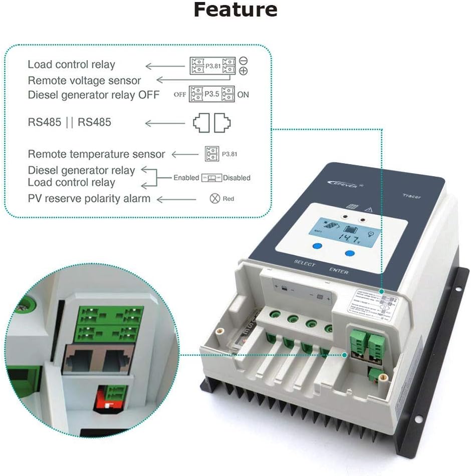
Figure 6.1: Diagram illustrating various features and connections, including Load control relay, Remote voltage sensor, Diesel generator relay control, RS485 communication, Remote temperature sensor, and PV reverse polarity alarm indication.
6.3 Application Examples
The EPEVER Tracer-AN series is versatile and can be used in a variety of solar power applications.

Figure 6.2: Examples of typical applications for the solar charge controller, including residential rooftop solar installations, off-grid cabins, and solar street lighting systems.
7. Specifications
Detailed technical specifications for the EPEVER Tracer-AN Series MPPT Solar Charge Controller (Tracer10415AN model) are provided below. This table includes parameters for various models in the series for comparison.
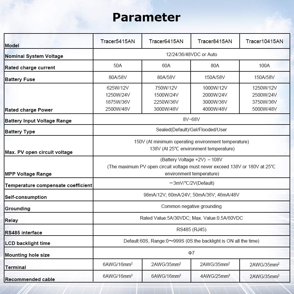
Figure 7.1: Comprehensive parameter table for Tracer-AN Series models, including Tracer5415AN, Tracer6415AN, Tracer8415AN, and Tracer10415AN. Key specifications include:
| Parameter | Tracer5415AN | Tracer6415AN | Tracer8415AN | Tracer10415AN |
|---|---|---|---|---|
| Nominal System Voltage | 12/24/36/48VDC or Auto | |||
| Rated charge current | 50A | 60A | 80A | 100A |
| Battery Fuse | 80A/58V | 80A/58V | 150A/58V | 150A/58V |
| Rated charge Power | 625W/12V, 1250W/24V, 1875W/36V, 2500W/48V | 750W/12V, 1500W/24V, 2250W/36V, 3000W/48V | 1000W/12V, 2000W/24V, 3000W/36V, 4000W/48V | 1250W/12V, 2500W/24V, 3750W/36V, 5000W/48V |
| Battery Input Voltage Range | 8V-68V | |||
| Battery Type | Sealed(Default)/Gel/Flooded/User | |||
| Max. PV open circuit voltage | 150V (At minimum operating environment temperature), 138V (At 25°C environment temperature) | |||
| MPP Voltage Range | (Battery Voltage +2V) ~ 108V | |||
| Temperature compensate coefficient | -3mV/°C/2V(Default) | |||
| Self-consumption | 98mA/12V, 60mA/24V, 50mA/36V, 46mA/48V | |||
| Grounding | Common negative grounding | |||
| Relay | Rated Value 5A/30VDC; Max. Value: 0.5A/60VDC | |||
| RS485 interface | RS485 (RJ45) | |||
| LCD backlight time | Default: 60S, Range 0~999S (0S: the backlight is ON all the time) | |||
| Mounting hole size | Φ7 | |||
| Terminal | 6AWG/16mm² | 6AWG/16mm² | 2AWG/35mm² | 2AWG/35mm² |
| Recommended cable | 6AWG/16mm² | 6AWG/16mm² | 4AWG/25mm² | 2AWG/35mm² |
8. Maintenance
Regular maintenance ensures the longevity and optimal performance of your EPEVER solar charge controller.
- Cleanliness: Keep the controller clean and free from dust and debris. Use a dry cloth to wipe the exterior.
- Connections: Periodically check all wiring connections for tightness and corrosion. Loose connections can cause overheating and poor performance.
- Ventilation: Ensure that the heat sink fins are not obstructed and that there is adequate airflow around the controller for proper heat dissipation.
- Indicators: Monitor the LED indicators and LCD display for any fault codes or unusual readings. Refer to the troubleshooting section if any issues arise.
- Battery Health: Regularly check the health and voltage of your batteries, as their condition directly impacts the system's performance.
9. Troubleshooting
This section addresses common issues you might encounter with your solar charge controller. For more complex problems, contact customer support.
9.1 Common Issues and Solutions
- Controller Not Charging:
- Check PV array connections and ensure solar panels are receiving sufficient sunlight.
- Verify battery connections and voltage. The controller requires a minimum battery voltage to start.
- Inspect fuses on the battery line for continuity.
- Low Charging Current:
- Ensure PV array is not shaded and is clean.
- Check for loose or corroded connections in the PV or battery wiring.
- Verify that the battery type setting in the controller matches your actual battery type.
- Controller Overheating:
- Ensure adequate ventilation around the controller. Do not install in an enclosed space without airflow.
- Check if the ambient temperature exceeds the controller's operating range.
- Verify that the PV input power does not exceed the controller's maximum rated power.
- Battery Not Holding Charge / BMS Tripping:
- As noted by a user, ensure all batteries in a bank are balanced and at similar voltage levels, especially for multi-battery systems. Imbalanced batteries can cause issues with the Battery Management System (BMS) and affect charging.
- Verify battery health and age.
9.2 Frequently Asked Questions (FAQs)
- Q: How to choose a solar controller with the appropriate specifications?
- A: The controller you purchase must meet two conditions:
- The rated current of the controller must be greater than (the power of the solar panel divided by the voltage of the battery).
- The open circuit voltage of the controller must be greater than the open circuit voltage of your solar panel, and both must be greater than the voltage of your battery.
10. Warranty and Support
EPEVER products are designed for reliability and performance. For specific warranty terms and conditions, please refer to the warranty card included with your product or visit the official EPEVER website.
For technical support, troubleshooting assistance, or service inquiries, please contact EPEVER customer support through their official channels. You can also visit the EPEVER Store on Amazon for additional resources and contact information.


