1. Introduction
The EPEVER MT-1 Remote Meter is designed for use with EPEVER EPIPDB-COM series dual battery solar charge controllers. It provides real-time monitoring of system status and parameters through its LCD display, offering convenient access to essential information and settings. This manual provides instructions for the proper installation, operation, and maintenance of the MT-1 remote meter.
2. Product Overview
2.1 Features
- Real-time display of system status and parameters with digital and graphic icons.
- LED indicators for charging status (green) and error conditions (red).
- Selectable battery type and adjustable battery Ah setting function.
- Adjustable temperature compensation coefficient.
- LCD display with two levels of brightness for enhanced visibility.
- Monitors voltage, currents, amp-hours, and watt-hours.
2.2 Package Contents
Upon unpacking, please verify that all items listed below are present and in good condition:
- 1 x EPEVER MT-1 Remote Meter
- 1 x RJ45 Communication Cable (Standard 10m)
- 1 x User Manual for MT-1

Figure 2.2.1: EPEVER MT-1 Package Contents
3. Setup and Installation
3.1 Physical Dimensions
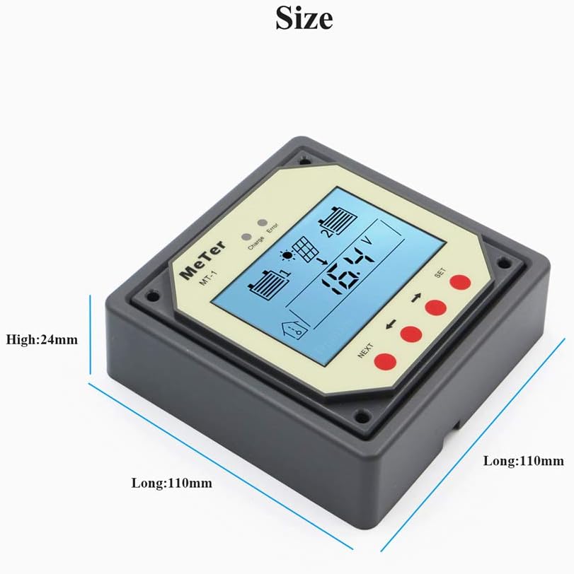
Figure 3.1.1: MT-1 Remote Meter Dimensions
The faceplate dimensions are approximately 2.75 x 1.75 inches (70 x 44.5 mm). The frame dimensions are approximately 3.74 x 3.74 inches (95 x 95 mm). The meter can be mounted in or on a wall using the provided mounting board.
3.2 Connection Wiring
The MT-1 Remote Meter connects to the EPIPDB-COM series solar charge controller via a standard RJ45 (8PIN) communication cable. Ensure the cable is securely plugged into the designated ports on both the remote meter and the solar charge controller.

Figure 3.2.1: Connection Diagram
4. Operating Instructions
4.1 Remote Meter Display
The LCD provides a visual interface for monitoring and configuring the solar charge controller. Key icons and indicators are explained below:
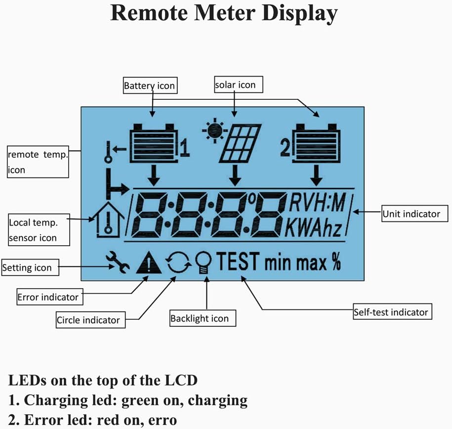
Figure 4.1.1: LCD Display Overview
- Battery Icon: Indicates the status and charge level of the connected batteries (Battery 1 and Battery 2).
- Solar Icon: Represents the solar panel input.
- Remote Temp. Icon: Indicates the remote temperature sensor is active.
- Local Temp. Sensor Icon: Indicates the internal temperature sensor is active.
- Setting Icon: Appears when in settings mode.
- Error Indicator: Displays when an error condition is detected.
- Backlight Icon: Indicates backlight status.
- Unit Indicator: Shows the unit of the displayed value (e.g., V for Volts, A for Amps, KWh for kilowatt-hours).
- Self-test Indicator: Appears during system self-test.
4.2 LED Indicators
Located at the top of the LCD, two LEDs provide quick status updates:
- Charging LED (Green): Illuminates when the system is actively charging.
- Error LED (Red): Illuminates when an error condition is present.
5. Maintenance
The EPEVER MT-1 Remote Meter is designed for low maintenance. To ensure optimal performance and longevity:
- Keep the display clean using a soft, dry cloth. Avoid abrasive cleaners or solvents.
- Ensure all cable connections (RJ45) are secure and free from corrosion.
- Avoid exposing the unit to extreme temperatures or direct moisture beyond its specified operating conditions.
- Regularly check the solar charge controller for any error indications that might affect the remote meter's readings.
6. Troubleshooting
If the error LED illuminates or the display shows unusual readings, consider the following common issues:

Figure 6.1.1: Troubleshooting Information
- Error Indicator (Red LED or Display Symbol): If the error symbol appears, check the system connections. The symbol should disappear automatically once the issue is resolved.
- Battery Disconnect, Open Circuit, or Over Voltage: Verify that both batteries are properly connected and within their operational voltage range. Check for any open circuits in the wiring.
- Remote Temperature Sensor Not Detected: Ensure the remote temperature sensor (if used) is correctly plugged in and functioning.
- Over Charging Current: This indicates the solar input current exceeds the controller's capacity. Review your solar panel configuration relative to your controller's specifications.
- No Display/Power: Check the RJ45 cable connection to the solar charge controller. Ensure the controller itself is powered and functioning correctly.
7. Specifications
| Rated Voltage | 12V (minimum suggested: 8V) |
| Strong Backlight ON Current | <23mA |
| Low Backlight ON Current | <20mA |
| Backlight and LED Indicator OFF Current | <17mA |
| Faceplate Dimensions | 2.75 x 1.75 inches (70 x 44.5 mm) |
| Frame Dimensions | 3.74 x 3.74 inches (95 x 95 mm) |
| Connector Type | RJ45 (8PIN) |
| Meter Cable Length | Standard 10m |
| Operation Temperature | -40°C to 60°C (-40°F to 140°F) |
| LCD Operation Temperature | -10°C to 40°C (14°F to 104°F) |
| Humidity | 0-100% (non-condensing) |
8. Warranty and Support
Warranty information for the EPEVER MT-1 Remote Meter is typically provided with the accompanying EPIPDB-COM series solar charge controller or can be obtained directly from the manufacturer, EPEVER, or the authorized seller. Please refer to the documentation included with your primary solar charge controller for specific warranty terms and conditions.
For technical support or inquiries, please contact your product vendor or visit the official EPEVER website for customer service resources.