
EPEVER Tracer 2215BN
EPEVER Tracer 2215BN MPPT Solar Charge Controller User Manual
Model: Tracer 2215BN
1. Introduction
The EPEVER Tracer 2215BN is a 20A Maximum Power Point Tracking (MPPT) solar charge controller designed for 12V/24V automatic system voltage detection. It efficiently manages power from solar panels to charge various battery types, including Sealed, Gel, Flooded, and User-defined lead-acid batteries. This controller features advanced MPPT technology, ensuring high conversion efficiency and reliable performance for off-grid solar systems.
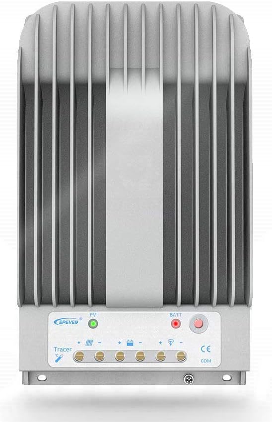
Figure 1.1: Front view of the EPEVER Tracer 2215BN MPPT Solar Charge Controller, showing its robust design and connection terminals.
Key Features:
- Advanced MPPT Technology: Ensures maximum power point tracking efficiency of no less than 99.5%, optimizing solar energy harvest.
- High Conversion Efficiency: Achieves a maximum conversion efficiency of 98% due to high-quality components.
- Automatic Limit Function: Reliable automatic limit function for maximum PV input power, preventing overload.
- Multiple Load Control Modes: Supports manual control, light ON/OFF, light On+Timer, and time control for versatile application.
- Battery Compatibility: Compatible with Sealed, Gel, Flooded, and User-defined lead-acid battery types.
- Communication Interface: Equipped with RS-485 communication bus interface and Modbus communication protocol for monitoring and parameter setting via PC or external display units like MT50.
- Common Negative Design: Based on common negative design for enhanced system compatibility.
- Die-cast Aluminum Design: Provides excellent heat dissipation characteristics.

Figure 1.2: Detailed diagram highlighting the key features and ports of the controller, including the heat sink, RTS port, charging LED indicator, battery LED indicator, button, RS-485 port, solar terminal, battery terminal, and load terminal.
Tracer-BN Series Advantages:
The Tracer-BN series, including the 2215BN, offers significant improvements over previous designs like the Tracer-AN series, particularly in heat dissipation and voltage ranges. Its die-cast aluminum design ensures superior thermal performance, allowing for a wider operating temperature range and higher maximum PV open circuit voltage.

Figure 1.3: Comparison illustrating the differences between Tracer-AN and Tracer-BN series, highlighting the improved heat dissipation, higher maximum PV open circuit voltage, wider MPP voltage range, and extended working and storage temperature ranges of the Tracer-BN series.
2. Setup and Installation
Proper installation is crucial for the safe and efficient operation of your EPEVER Tracer 2215BN controller. Please follow the steps below carefully. Always ensure all power sources are disconnected before making any connections.
Installation Sequence:
- Connect Battery: Always connect the battery to the charge controller first. This allows the controller to recognize the system voltage (12V or 24V). Ensure correct polarity (+ to + and - to -). The battery fuse should be installed as close to the battery as possible, ideally within 150mm.
- Connect Solar Panels (PV Array): Connect the solar panels to the controller. Ensure the PV open circuit voltage does not exceed the controller's maximum input voltage (150V). Observe correct polarity.
- Connect Load: Connect your DC loads to the load terminals of the controller.
Important Safety Notes:
- Pay close attention to the "+" and "-" polarities during all connections.
- Do not turn on the fuse or circuit breakers during installation.
- When disconnecting the system, reverse the installation order (disconnect load, then PV, then battery).
- The Tracer-BN series is a negative ground controller. Any negative connection of solar, load, or battery can be earth grounded as required.
- If an inverter is necessary, connect it directly to the battery, not to the controller.

Figure 2.1: Comprehensive wiring diagram illustrating the connection of solar panels, battery, and various DC loads (e.g., light, fan, TV, computer, speakers) to the EPEVER Tracer 2215BN controller. An inverter is shown connected directly to the battery for AC loads.
3. Operating Instructions
Once installed, the Tracer 2215BN operates automatically to manage your solar charging. Understanding its indicators and control options will help you optimize your system.
LED Indicators:
- PV Indicator: Shows the status of solar panel input and charging.
- Battery Indicator: Displays battery charge status and system voltage.
- Load Indicator: Indicates the status of the DC load output.
Load Control Modes:
The controller offers several modes for managing the DC load output:
- Manual Control: Turn the load ON/OFF manually via the controller's button or connected display unit.
- Light ON/OFF: Load turns on at dusk and off at dawn.
- Light On+Timer: Load turns on at dusk and stays on for a set duration.
- Time Control: Load operates during specific programmed time periods.
Battery Charging Options:
The controller supports 4 charging options, which can be selected based on your battery type:
- Sealed Lead-Acid Battery
- Gel Lead-Acid Battery
- Flooded Lead-Acid Battery
- User-defined (customizable parameters)
Communication and Monitoring:
The Tracer 2215BN is equipped with communication interfaces for advanced monitoring and control:
- RS-485 Port: Allows connection to a PC for real-time data checking, parameter setting, and software upgrades using EPEVER's monitoring software.
- RTS Port: Remote Temperature Sensor port for accurate battery temperature compensation, ensuring optimal charging. If the RTS is unplugged, the battery temperature will be fixed at 25°C.
- External Display Unit (e.g., MT50): Connect an MT50 meter for convenient real-time data display and parameter adjustment without needing a PC.
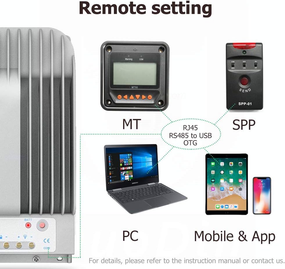
Figure 3.1: Illustration of remote setting options, including connection to an MT50 display unit, PC via RS485 to USB OTG, and mobile devices via app, enabling comprehensive monitoring and control.

Figure 3.2: Close-up view of the RTS (Remote Temperature Sensor) port and the RS-485 communication port, highlighting their physical locations on the controller for connectivity.
4. Maintenance
Regular maintenance ensures the longevity and optimal performance of your EPEVER Tracer 2215BN controller and the entire solar system.
- Inspect Connections: Periodically check all wiring connections for tightness and corrosion. Loose connections can cause overheating and performance issues.
- Clean the Controller: Keep the controller clean and free from dust and debris. Ensure the heat sink fins are not obstructed to allow for proper heat dissipation. Use a dry cloth for cleaning.
- Check Indicators: Regularly observe the LED indicators to ensure normal operation. Refer to the operating instructions for indicator meanings.
- Battery Health: Monitor your battery's health and electrolyte levels (for flooded batteries) as per the battery manufacturer's guidelines. Ensure the battery temperature sensor (RTS) is properly connected and positioned for accurate temperature compensation.
- Environmental Conditions: Ensure the controller is installed in a well-ventilated area, away from direct sunlight, moisture, and corrosive environments.
5. Troubleshooting
This section provides guidance for common issues you might encounter with your Tracer 2215BN controller. For more complex problems, consult a qualified technician or contact EPEVER support.
| Problem | Possible Cause | Solution |
|---|---|---|
| Controller not powering on / No lights |
|
|
| No charging from PV array |
|
|
| Load not working |
|
|
6. Specifications
Detailed technical specifications for the EPEVER Tracer 2215BN MPPT Solar Charge Controller.
| Parameter | Value |
|---|---|
| Model | Tracer 2215BN |
| Rated Charge Current | 20A |
| System Voltage | 12V/24V Auto Recognition |
| Max. PV Open Circuit Voltage | 150V |
| Max. PV Input Power | 260W (12V) / 520W (24V) |
| Battery Type | Sealed, Gel, Flooded, User |
| Grounding | Common Negative |
| Communication Port | RS-485 |
| Operating Temperature Range | -35°C to +55°C |
| Storage Temperature Range | -35°C to +80°C |
| Dimensions (L x W x H) | 303mm x 183mm x 64mm (approx. 11.93 x 7.20 x 2.52 inches) |
| Item Weight | 3.32 pounds |
| UPC | 732376583374 |

Figure 6.1: Dimensional drawing of the controller, indicating its length (L), width (W), and height (H) for installation planning. Note: The image shows 4215BN, but dimensions are representative for the series.
7. Warranty and Support
Information regarding product warranty and customer support for your EPEVER Tracer 2215BN controller.
Warranty Information:
Based on available information, explicit warranty details from the manufacturer (EPEVER) are not readily provided in the product documentation or on their public-facing website. Some users have reported difficulty in finding clear warranty statements or contact information for support.
It is recommended to retain your proof of purchase and contact the seller directly for any warranty-related inquiries or issues that may arise within a reasonable period after purchase. Additionally, check with your credit card provider, as some offer extended warranty benefits on purchases.
Customer Support:
For technical assistance, troubleshooting beyond this manual, or product inquiries, please refer to the contact information provided by your point of purchase (the seller). You may also attempt to visit the official EPEVER website for general product information or potential support channels, though direct contact information may vary.
When seeking support, please have your product model (Tracer 2215BN), purchase date, and a detailed description of the issue ready.
Related documentsTracer 2215BN


Ask a question about this manual
Ask about setup, troubleshooting, compatibility, parts, safety, or missing instructions. Manuals+ will review the question and use this page’s manual context to help answer it.