
EPEVER Triron2210n+mt50+rts+rs485
Contents
EPEVER Triron N Series MPPT Solar Charge Controller User Manual
Model: Triron2210n Set (Triron2210n+MT50+RTS+RS485)
1. Introduction
The EPEVER Triron N series MPPT solar charge controller is a modular-designed device engineered for efficient and reliable solar power management. Utilizing advanced Maximum Power Point Tracking (MPPT) control algorithms, it minimizes power loss and quickly tracks the maximum power point of photovoltaic (PV) arrays, ensuring optimal energy harvesting from solar modules under various conditions. This controller is designed with negative grounding, making it suitable for a wide range of applications including communication base stations, household solar systems, street lighting, field monitoring, and RV solar setups.
The Triron2210n model automatically identifies 12V or 24V DC system voltages and features a rated charging/discharging current of 20A. It supports a maximum open circuit voltage of 100V and a maximum PV power input of 260W for 12V systems or 520W for 24V systems. It is compatible with both lead-acid and lithium batteries.
2. Product Features
The EPEVER Triron N series controllers offer significant advancements and features for robust solar power management:
- Advanced MPPT Technology: Ensures maximum power harvesting from solar panels with high tracking efficiency.
- Negative Grounding Design: Provides versatility for various system configurations, supporting both positive and negative grounding.
- Automatic System Voltage Recognition: Automatically detects 12V or 24V DC system voltage.
- Wide Battery Compatibility: Supports Sealed, Gel, Flooded, LiFePO4, Li-NiCoMn, and User-defined battery types.
- Adaptive Three-Stage Charging: Optimizes battery charging to prolong battery life.
- Enhanced Heat Dissipation: Designed for better thermal management, ensuring stable operation.
- Detailed LCD Display: Provides comprehensive parameters including PV voltage/current, generated energy, battery voltage/current/temperature/capacity, and load status.
- User-Friendly Interface: Features 5 buttons for easy viewing and setting of parameters.
- Modular Design with Hot Swapping: Allows for easy replacement and upgrade of components.
- Remote Monitoring and Control: Includes the MT50 remote meter for real-time data monitoring, parameter browsing, and modification of load switch, device, charging, and load control parameters.
- Temperature Compensation: Remote Temperature Sensor (RTS) provides accurate temperature compensation for charging, extending battery lifespan.
- Real-Time Energy Statistics: Functionality for tracking energy data.
- Dual USB Output: Two 5V/2.2A USB ports for direct charging of electronic devices.
- Comprehensive Electronic Protections: Minimizes damage from incorrect installation or system failure, ensuring safer operation.

Figure 2.1: Comparison illustrating key upgrades and improvements of the Triron N series over previous models.
3. Components and Package Contents
The EPEVER Triron2210n Set includes the following core components:
- EPEVER Triron2210n MPPT Solar Charge Controller
- MT50 Remote Meter
- Remote Temperature Sensor (RTS)
- RS485 Communication Cable

Figure 3.1: Main components of the Triron2210n set, including the solar charge controller, MT50 remote display, RS485 communication cable, and temperature sensor.

Figure 3.2: Detailed view of the MT50 remote meter, RS485 communication cable, and Remote Temperature Sensor (RTS).
The Triron N series controllers feature a modular design, allowing for easy replacement and upgrade of certain components. The main controller unit has slots for various modules, enhancing its flexibility and serviceability.

Figure 3.3: Illustration of the Triron N series' removable and modular components, highlighting ease of maintenance and customization.
Optional accessories, such as additional display modules (DB1, DSI), relay modules (RCM, RCS), and USB communication modules (USB1), can be purchased separately to expand the controller's functionality.

Figure 3.4: Overview of replaceable product accessories and optional modules for the Triron N series controller.
4. Setup and Installation
Proper installation is crucial for the safe and efficient operation of your solar charge controller. Always ensure all power sources are disconnected before making any connections.
4.1 Connection Order
Follow this connection sequence to prevent damage to the controller and other components:
- Connect the Battery: First, connect the battery to the controller's battery terminals. Ensure correct polarity (positive to positive, negative to negative). The controller will detect the system voltage.
- Connect the Solar Panels (PV Array): Next, connect the solar panels to the controller's PV terminals. Ensure correct polarity. The controller will begin charging the battery.
- Connect the Load (Optional): Finally, connect your DC load to the controller's load terminals, if applicable.
Important: Always connect the battery first and disconnect it last. This ensures the controller initializes correctly and prevents potential damage from reverse polarity or voltage surges.
4.2 Peripheral Connections
- MT50 Remote Meter: Connect the MT50 remote meter to the controller's communication port (usually an RJ45 port) using the provided cable. This allows for remote monitoring and parameter adjustment.
- Remote Temperature Sensor (RTS): Plug the RTS into the designated temperature sensor port on the controller. This sensor provides accurate battery temperature readings for optimal charging compensation. If not connected, the controller defaults to 25°C for compensation.
- RS485 Communication Cable: Use the RS485 cable to connect the controller to a PC for monitoring and configuration via software, or to other compatible devices.

Figure 4.1: System connection diagram illustrating how to connect solar panels, battery, DC load, and communication accessories to the Triron N controller.
5. Operating Instructions
Once installed, the Triron2210n controller operates automatically to manage your solar charging system. The MT50 remote meter provides a user-friendly interface for monitoring and control.
5.1 MT50 Remote Meter Operation
The MT50 meter allows you to view real-time data, browse historical information, and modify various parameters of the controller. The LCD display shows critical system information such as PV voltage, current, generated energy, battery voltage, charging current, load status, and more.
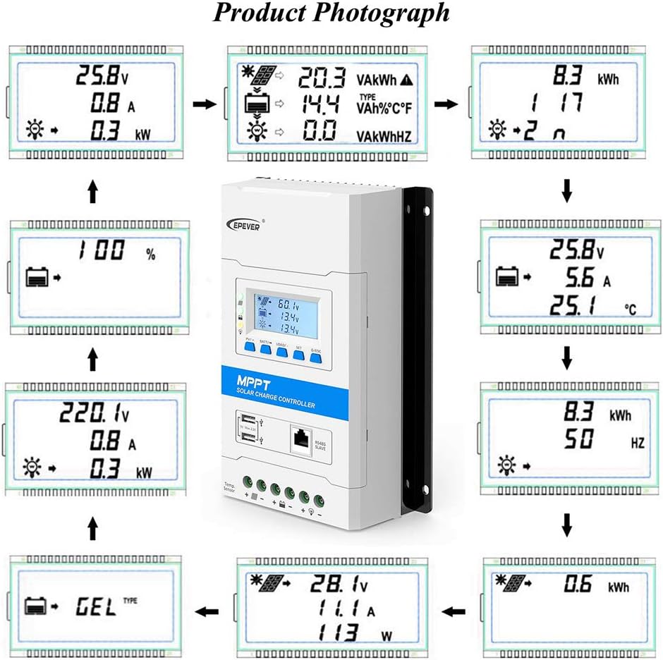
Figure 5.1: Examples of information displayed on the controller's LCD screen, including PV input, battery status, and load output.
Use the buttons on the MT50 to navigate through different display screens and access menus for parameter settings. Refer to the MT50 user manual for detailed instructions on menu navigation and parameter modification.
5.2 Charging Modes
The controller employs an adaptive three-stage charging mode (Bulk, Boost, Float) to optimize battery charging and extend its lifespan. The specific charging voltages are adjusted based on the selected battery type and temperature compensation from the RTS.
5.3 USB Output
The dual USB output ports (5V/2.2A) on the controller can be used to directly charge small electronic devices such as smartphones or tablets.
5.4 Software Monitoring (Optional)
For advanced monitoring and configuration, the controller can be connected to a PC via the RS485 cable or to an Android device using an optional eBox-WIFI-01 or eBox-BLE-01 module. This allows for detailed data logging, parameter adjustments, and firmware updates.
6. Maintenance
Regular maintenance ensures the longevity and optimal performance of your EPEVER solar charge controller.
- Cleanliness: Keep the controller clean and free from dust and debris. Ensure ventilation openings are not blocked to allow for proper heat dissipation.
- Connection Checks: Periodically inspect all wiring connections (battery, PV, load) to ensure they are secure and free from corrosion. Loose connections can lead to power loss or overheating.
- Battery Health: Monitor your battery's health and voltage regularly. Ensure the battery type setting in the controller matches your installed battery.
- Temperature Sensor: Ensure the Remote Temperature Sensor (RTS) is properly connected and positioned near the battery for accurate temperature compensation.
7. Troubleshooting
If you encounter issues with your EPEVER solar charge controller, consider the following common troubleshooting steps:
- No Display/Power:
- Check battery connections and ensure correct polarity.
- Verify battery voltage is within the controller's operating range (8-32V).
- No Charging:
- Check PV panel connections and ensure correct polarity.
- Verify PV open circuit voltage is within the controller's limits (Max 100V).
- Ensure there is sufficient sunlight on the solar panels.
- Check if the PV input power exceeds the controller's maximum input power.
- Load Not Working:
- Check load connections and ensure correct polarity.
- Verify the load current does not exceed the controller's rated load current (20A).
- Check load control settings on the MT50 or software (e.g., dusk-to-dawn, timer).
- Ensure battery voltage is above the low voltage disconnect (LVD) setting.
- Inaccurate Readings:
- Ensure the RTS is properly connected for accurate temperature compensation.
- Verify battery type settings match your battery.
For more detailed troubleshooting or persistent issues, please refer to the comprehensive user manual provided by EPEVER or contact their customer support.
8. Specifications
Key technical specifications for the EPEVER Triron2210n MPPT Solar Charge Controller:

Figure 8.1: Electrical parameters table for the Triron N series, highlighting specifications for different models including the Triron2210N.
| Parameter | Value (Triron2210n) |
|---|---|
| Nominal System Voltage | 12/24VDC Auto work |
| Rated Charge Current | 20A |
| Rated Discharge Current | 20A |
| Battery Input Voltage Range | 8~32V |
| Max. PV Open Circuit Voltage | 100V |
| Max. PV Input Power | 260W (12V) / 520W (24V) |
| Battery Type Compatibility | Sealed, Gel, Flooded, LiFePO4, Li-NiCoMn, User-defined |
| USB Output | 5VDC/2.2A (Dual) |
| Dimensions (Controller) | Approx. 26.2 x 18.7 x 15.3 cm (Parcel Dimensions) |
| Weight (Controller) | Approx. 1.8 kg (Parcel Weight) |
| Manufacturer | EPEVER |
| UPC | 732376583343 |
9. Warranty and Support
For warranty information, technical support, or service inquiries regarding your EPEVER Triron N series solar charge controller, please contact EPEVER customer service directly or refer to the official EPEVER website. Ensure you have your product model number (Triron2210n) and purchase details available when seeking support.
For additional resources and software downloads, visit the official EPEVER support page.
Ask a question about this manual
Ask about setup, troubleshooting, compatibility, parts, safety, or missing instructions. Manuals+ will review the question and use this page’s manual context to help answer it.