
EPEVER TRIRON 3210N
EPEVER TRIRON 3210N MPPT Solar Charge Controller User Manual
Intelligent Modular-Designed Regulator for 12V/24V Solar Systems
1. Product Overview
The EPEVER TRIRON N series solar charge controller is a modular-designed Maximum Power Point Tracking (MPPT) device engineered for efficient solar energy management. It is an updated version of the Tracer A/AN Series, offering enhanced features and performance.
Utilizing an advanced MPPT control algorithm, the TRIRON N series minimizes power loss and quickly tracks the maximum power point of your PV array, ensuring optimal energy harvest from solar modules under various conditions. Its adaptive three-stage charging mode, based on a digital control circuit, extends battery life and significantly improves system performance. The controller also includes comprehensive electronic protection functions to prevent damage from incorrect installation or system failures, ensuring safe and reliable operation of your solar power system.

Figure 1.1: EPEVER TRIRON 3210N MPPT Solar Charge Controller. This image shows the front of the controller with its LCD display, buttons, USB ports, and connection terminals.
2. Key Features
- Modular Design: Allows for easy combination and replacement of different display and interface modules, supporting hot-swapping.
- Advanced MPPT Technology: Features an efficiency of no less than 99.5%, minimizing MPP loss rate and time.
- Versatile Battery Compatibility: Supports 7 battery types including Sealed (AGM), Gel, Flooded, Lead-acid User, LiFePO4 Lithium, Li(NiCoMn)O2 Lithium, and Lithium User (9~34V).
- Negative Ground Design: Suitable for various applications such as communication base stations, household systems, street lighting, field monitoring, and RV solar systems.
- Dual USB Output: Provides 5V DC / 2.2A power for direct charging of electronic devices.
- RS485 Communication: Master and slave RS485 communication modules for reading load or inverter operating data.
- Intuitive Display & Control: Three color indicators for PV/Battery/Load status and five buttons for easy adjustment and browsing of system parameters.
- Improved Heat Dissipation: Enhanced design for better thermal management compared to previous models.

Figure 2.1: Comparison of Tracer A/AN Series and TRIRON N Series. This table highlights the upgrades in the TRIRON N series, including better heat dissipation, more detailed LCD display, more buttons, modular replacement capability, and dual USB output.
3. Package Contents
Upon opening the package, please verify that all items are present and undamaged:
- 1 x EPEVER TRIRON N Series Solar Charge Controller (TRIRON 3210N)
- 1 x User Manual
4. Safety Instructions
Please read and understand these safety instructions before installation and operation to prevent injury or damage to the controller and other components.
- Wiring Precautions: When wiring the controller, ensure that the circuit breaker or fuse is open (disconnected) and verify that the positive ("+") and negative ("-") poles of the leads are connected correctly. Incorrect polarity can cause severe damage.
- Battery Fuse Installation: A fuse with a current rating 1.25 to 2 times the rated current of the controller must be installed on the battery side. This fuse should be located no more than 150 mm (approximately 6 inches) from the battery terminal.
- Inverter Connection: If an inverter is to be connected to your solar system, connect the inverter directly to the battery terminals. Do not connect the inverter to the load side of the controller.
- Ensure all connections are tight and secure to prevent loose contacts and overheating.
- Install the controller in a well-ventilated area, away from flammable materials and direct sunlight.
5. Setup and Installation
Follow these steps for proper installation of your EPEVER TRIRON 3210N solar charge controller. Refer to Figure 5.1 for a visual representation of the system connections.
- Mounting the Controller: Choose a suitable location for mounting the controller. It should be in a dry, well-ventilated area, protected from direct sunlight and moisture. Ensure there is adequate space around the controller for air circulation and heat dissipation.
- Connect the Battery: First, connect the battery to the controller's battery terminals (marked with a battery symbol). Ensure correct polarity: connect the battery's positive terminal to the controller's positive battery terminal, and the battery's negative terminal to the controller's negative battery terminal. The controller will power on once the battery is connected.
- Connect the Solar Panels (PV Array): Next, connect the solar panels to the controller's PV terminals (marked with a solar panel symbol). Again, observe correct polarity: connect the solar panel's positive output to the controller's positive PV terminal, and the solar panel's negative output to the controller's negative PV terminal.
- Connect the DC Load (Optional): If you have DC loads, connect them to the controller's load terminals (marked with a light bulb symbol). Ensure correct polarity. The controller will manage power delivery to these loads.
- Connect Optional Modules/Accessories: The TRIRON N series supports various optional modules such as display units (DB1, DSI), relay modules (RCM, RCS), and USB communication modules (USB1). These can be integrated into the modular slots on the controller. Refer to Figure 5.2 for examples of replaceable accessories.
- Connect Temperature Sensor (Optional): For accurate battery charging, connect the external temperature sensor to the designated port on the controller. This helps the controller adjust charging parameters based on ambient temperature.
- Power On: Once all connections are secure and verified for correct polarity, you can close the circuit breakers or fuses for the battery and solar array. The controller's display will activate, showing system parameters.

Figure 5.1: Product Function Diagram. This diagram illustrates the typical connections for the solar charge controller, including solar panels, battery, DC load, and various communication interfaces (RJ45-USB, RJ45-USB-OTG, RJ45-RJ45) for connecting to laptops, mobile apps, or remote meters (MT50).

Figure 5.2: Replaceable Product Accessories. This image shows the modular design of the TRIRON N series, highlighting optional accessories like display modules (DB1, DSI), relay modules (RCM, RCS), and a USB communication module (USB1) that can be added or replaced.

Figure 5.3: Removable Collocation. This image further demonstrates the modularity, showing the main controller unit disassembled into its core components and optional modules, emphasizing ease of assembly and replacement.
6. Operating Instructions
The EPEVER TRIRON 3210N controller features an intuitive LCD display and five buttons for easy operation and monitoring. The display provides real-time data on your solar system's performance.
6.1 LCD Display and Indicators
The LCD screen cycles through various parameters, providing comprehensive information about the PV array, battery, and load. Three indicator lights (PV, Battery, Load) with different colors provide a quick visual status.
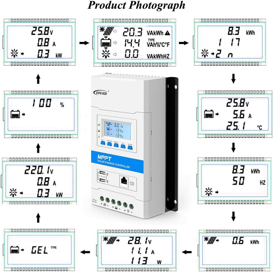
Figure 6.1: Product Photograph. This image displays a sequence of different screens on the controller's LCD, showing various parameters such as PV voltage, current, power, generated energy, battery voltage, current, temperature, capacity, and load status. It also shows battery type selection.
6.2 Button Functions
The five buttons on the controller allow you to navigate through the display menus and adjust system parameters.
- PV/+ Button: Typically used to scroll forward through PV-related parameters or increase values during settings.
- BATT/- Button: Typically used to scroll backward through battery-related parameters or decrease values during settings.
- LOAD Button: Used to control the DC load output (turn on/off) or navigate load-related parameters.
- SET Button: Used to enter setting mode for parameters or confirm selections.
- ESC Button: Used to exit setting mode without saving changes or return to the previous menu.
6.3 Parameter Settings
To adjust parameters such as battery type, load control mode, or charging voltages, press the SET button to enter the setting interface. Use the PV/+ and BATT/- buttons to navigate through options and adjust values. Press SET again to confirm, or ESC to cancel.
The controller supports 7 battery types: Sealed, Gel, Flooded, Lead-acid User, LiFePO4 Lithium, Li(NiCoMn)O2 Lithium, and Lithium User. Ensure the correct battery type is selected for optimal charging and battery longevity.
7. Maintenance
Regular maintenance ensures the longevity and optimal performance of your EPEVER TRIRON 3210N solar charge controller.
- Cleanliness: Keep the controller clean and free from dust and debris. Use a dry cloth to wipe the exterior. Do not use liquid cleaners.
- Connections: Periodically check all wiring connections to ensure they are tight and secure. Loose connections can lead to overheating and poor performance.
- Ventilation: Ensure that the ventilation openings on the controller are not blocked. Proper airflow is crucial for heat dissipation.
- Battery Inspection: Regularly inspect your battery bank for any signs of corrosion, swelling, or leakage. Ensure battery terminals are clean.
- System Performance: Monitor the system's performance through the controller's display or connected monitoring software. Note any unusual readings or behavior.
8. Troubleshooting
This section provides basic troubleshooting steps for common issues. For more complex problems, please refer to the detailed user manual or contact EPEVER customer support.
- Controller Not Powering On:
- Check battery connections and ensure correct polarity.
- Verify battery voltage is within the controller's operating range.
- Check the battery fuse for continuity.
- No Charging from Solar Panels:
- Ensure solar panel connections are secure and correct polarity.
- Check PV array voltage and current. Ensure it's above the battery voltage and within the controller's input range.
- Verify there is sufficient sunlight reaching the solar panels.
- Load Not Working:
- Check load connections and polarity.
- Ensure the load output is enabled on the controller (check LOAD button status).
- Verify battery voltage is not below the low voltage disconnect setting.
- Check if the load is overloaded or short-circuited.
- Inaccurate Readings:
- Ensure the external temperature sensor (if used) is properly connected and placed.
- Verify the correct battery type is selected in the controller settings.
9. Specifications
The following table provides detailed electrical parameters for the EPEVER TRIRON 3210N and other models in the series.
| Electrical parameters | TRIRON 1206N | TRIRON 2206N | TRIRON 1210N | TRIRON 2210N | TRIRON 3210N | TRIRON 4210N |
|---|---|---|---|---|---|---|
| Nominal system voltage | 12/24VDC auto work | |||||
| Rated charge current | 10A | 20A | 10A | 20A | 30A | 40A |
| Rated discharge current | 10A | 20A | 10A | 20A | 30A | 40A |
| Battery input voltage range | 8~32V | |||||
| Max. PV open circuit voltage | TRIRON**06N : 60Vat Min operating environment temp; 46Vat 25℃environment temp TRIRON**10N : 100Vat Min operating environment temp; 92Vat 25℃environment temp TRIRON**15N : 150Vat Min operating environment temp; 138Vat 25℃environment temp | |||||
| MPP voltage range | (Vbat+2V)~36V TRIRON**10N : (Vbat+2V)~72V TRIRON**15N : (Vbat+2V)~92V | |||||
| Max.PV input power | 130W/12V 260W/24V | 260W/12V 520W/24V | 130W/12V 260W/24V | 260W/12V 520W/24V | 390W/12V 780W/24V | 520W/12V 1040W/24V |
| Battery type | Sealed / Gel / Flooded; LiFePO4 / Li-NiCoMn / User | |||||
| Lead-acid batteries | Equalize charge voltage | Sealed: 14.6V, Flooded: 14.8V, User-defined: 9~17V | ||||
| Boost charge voltage | Gel: 14.2V, Sealed: 14.4V, Flooded: 14.6V, User-defined: 9~17V | |||||
| Float charge voltage | Gel/Sealed /Flooded: 13.8V, User-defined: 9~17V | |||||
| Low voltage reconnect voltage | Gel/Sealed /Flooded: 12.6V, User-defined: 9~17V | |||||
| Low voltage disconnect voltage | Gel/Sealed /Flooded: 11.1V, User-defined: 9~17V | |||||
| Li-battery | Boost charging voltage | LiFePO4:14.4V; Li-NiCoMn: 12.4V; User:9~17V | ||||
| Float charging voltage | LiFePO4:13.6V; Li-NiCoMn: 11.8V; User:9~17V | |||||
| Low voltage reconnect voltage | LiFePO4:12.4V; Li-NiCoMn: 10.40V; User:9~17V | |||||
| Low voltage disconnect voltage | LiFePO4:11.0V; Li-NiCoMn: 9.20V; User:9~17V | |||||

Figure 9.1: Electrical Parameters. This image provides a detailed table of electrical specifications for various TRIRON N series models, including nominal system voltage, rated charge/discharge current, battery input voltage range, max PV open circuit voltage, MPP voltage range, max PV input power, and detailed charging parameters for lead-acid and lithium batteries.
9.2 General Specifications (TRIRON 3210N)
- Manufacturer: EPEVER
- Model: TRIRON3210N
- Charging Port Type: USB (Dual 5V DC / 2.2A output)
- Package Dimensions: 11.34 x 7.13 x 3.86 inches
- Item Weight: 3.84 pounds
- ASIN: B081Q7B8DC
- Voltage: 24 Volts (DC)
- Display Type: LCD
- UPC: 732376583312

Figure 9.2: Product Size. This image provides the dimensions of the TRIRON 3210N controller: Length (L: 239mm), Width (W: 158mm), and Height (H: 63mm).
10. Warranty and Support
EPEVER products are designed for reliability and performance. For warranty information, technical support, or service inquiries, please contact EPEVER customer service directly or visit their official website.
When contacting support, please have your product model (TRIRON 3210N) and purchase details ready to assist with faster service.
Related documentsTRIRON 3210N


Ask a question about this manual
Ask about setup, troubleshooting, compatibility, parts, safety, or missing instructions. Manuals+ will review the question and use this page’s manual context to help answer it.