
1. Introduction
The EPEVER Tracer1210AN is a 10A Maximum Power Point Tracking (MPPT) solar charge controller designed for 12V/24V DC systems. It automatically identifies system voltage and features common negative grounding. This controller is compatible with various battery types, including lead-acid (sealed, gel, flooded) and lithium batteries (LiFePO4, Li(NiCoMn)O2, and user-defined). It incorporates advanced MPPT technology for high tracking efficiency and comprehensive protection functions to ensure system stability and battery longevity.
2. Key Features
- Rated Current: 10A charging and discharging.
- System Voltage: 12V/24V DC automatic identification.
- Max PV Input: 100V open circuit voltage; 130W/12V, 260W/24V power.
- Grounding: Common negative grounding.
- MPPT Technology: Advanced tracking speed with efficiency ≥99.5%.
- Battery Compatibility: Supports sealed, gel, flooded lead-acid, LiFePO4, Li(NiCoMn)O2, and user-defined lithium batteries.
- Load Control Modes: Manual, light on/off, light on + timer, and test mode.
- Display: Backlit LCD for real-time energy statistics and status.
- Communication: Standard Modbus protocol with RS485 for monitoring via mobile app (with EBox), PC software, or MT50 remote meter.
- Protection Functions: Battery temperature compensation, PV over current/power/reverse polarity, night reverse charge, battery over discharge, load short circuit, and overheating power reduction.
- Construction: Die-cast aluminum design for efficient heat dissipation.
3. Product Overview and Interface
The Tracer1210AN controller features a robust design with clearly labeled terminals and an intuitive LCD display for monitoring system status.
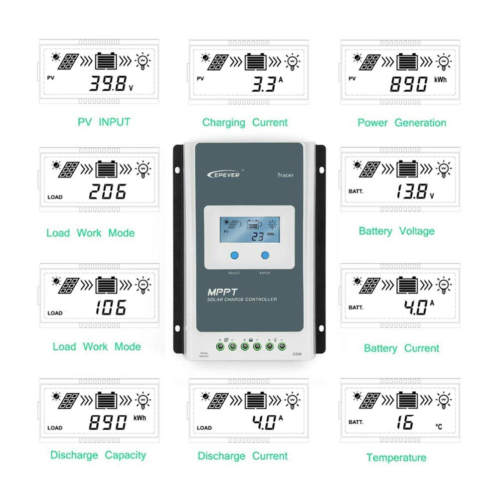
Figure 3.1: Controller Interface. This diagram illustrates the various components and connection points of the EPEVER Tracer1210AN solar charge controller, including the LCD display, selection buttons, remote temperature sensor port, solar panel terminals, battery terminals, load terminals, and the RJ45 communication port.
- Mounting Holes: For secure installation.
- LCD Display: Shows real-time system data.
- Select/Enter Buttons: For navigation and parameter settings.
- Remote Temp. Sensor: Port for connecting an external temperature sensor (RTS).
- Solar Panel Terminal: Connects to the solar PV array.
- Battery Terminal: Connects to the battery bank.
- Load Terminal: Connects to DC loads.
- RJ45 Communication Port: For connecting accessories like MT50, eBox-wifi, or PC communication cables.

Figure 3.2: Front View of the Tracer1210AN. This image shows the front panel of the EPEVER Tracer1210AN MPPT solar charge controller, highlighting its compact design and integrated LCD display.
4. Setup and Installation
Proper installation is crucial for the safe and efficient operation of your solar charge controller. Please follow these steps carefully.
4.1 Safety Precautions
- Ensure all connections are tight to avoid excessive heat buildup.
- Install the controller indoors, away from direct sunlight, high temperatures, and water.
- Mount the controller vertically on a wall or flat surface to allow for proper air circulation.
- Use appropriate circuit breakers or fuses for the solar panel, battery, and load circuits.
- Always connect the battery first, then the solar panel, and finally the load. Disconnect in reverse order.
4.2 Wiring Sequence
- Connect the Battery: Connect the battery to the controller's battery terminals. Ensure correct polarity (+ to + and - to -). The controller will detect the system voltage.
- Connect the Solar Panel: Connect the solar panel to the controller's PV terminals. Ensure correct polarity.
- Connect the DC Load: Connect the DC load to the controller's load terminals. Ensure correct polarity.
- Connect Remote Temperature Sensor (Optional): If using, connect the RTS to the designated port. This improves battery charging accuracy.
- Connect Communication Accessories (Optional): If using an MT50 remote meter, eBox-wifi, or PC communication cable, connect it to the RJ45 port.
Important: Incorrect wiring sequence can damage the controller. Always connect the battery first and disconnect the solar panel first.
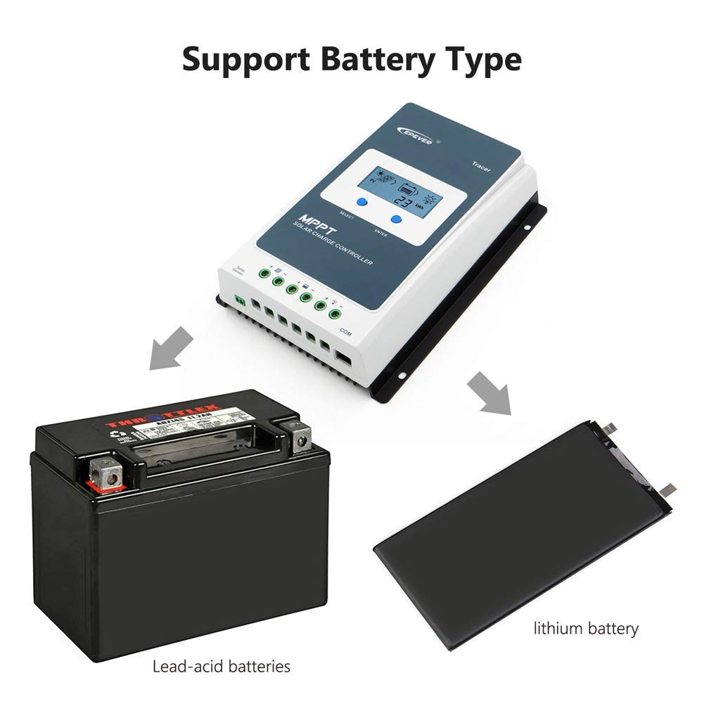
Figure 4.1: Wiring Terminals. This image shows the connection terminals for the solar panel, battery, and load on the EPEVER Tracer1210AN controller.
5. Operating Instructions
The Tracer1210AN controller features an LCD display and buttons for easy operation and monitoring.
5.1 LCD Display and Button Functions
The backlit LCD displays various system parameters. Use the "SELECT" and "ENTER" buttons to navigate menus and adjust settings.
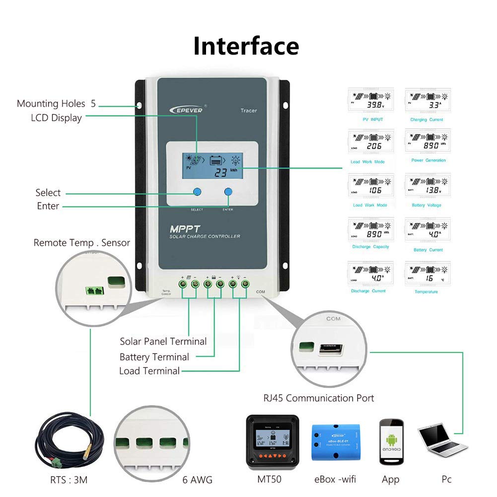
Figure 5.1: LCD Display. This image shows the LCD display of the Tracer1210AN, indicating various real-time parameters such as PV input, charging current, battery voltage, and load status.
5.2 Status Description
The LCD uses icons to indicate the current status of the solar array, battery, and load.
Figure 5.2: Status Icons. This table explains the meaning of various icons displayed on the controller's LCD, indicating conditions like day/night, charging status, battery type, and load operation.
5.3 Battery Type Settings
The controller supports various battery types. It is essential to select the correct battery type for optimal charging and discharge management.
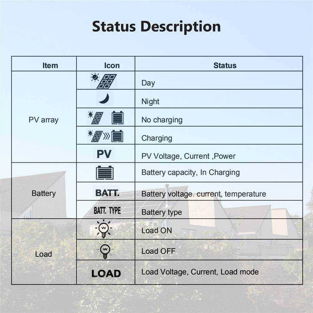
Figure 5.3: Supported Battery Types. This image shows the controller's compatibility with both lead-acid and lithium battery types.
- Lead-Acid: Sealed, Gel, Flooded.
- Lithium: LiFePO4, Li(NiCoMn)O2.
- User-Defined: Allows custom parameters for specific battery chemistries.
Refer to the detailed user manual (usually provided with the product or available online) for specific instructions on how to navigate the LCD menu and set battery parameters.
5.4 Load Control Modes
The controller offers four load control modes:
- Manual Mode: Load can be turned on/off manually.
- Light On/Off: Load turns on at dusk and off at dawn.
- Light On + Timer: Load turns on at dusk and stays on for a set duration.
- Test Mode: For testing load functionality.
6. Maintenance
Regular maintenance ensures the longevity and optimal performance of your EPEVER Tracer1210AN solar charge controller.
- Check Connections: Periodically inspect all wiring connections (solar panel, battery, load) to ensure they are tight and free from corrosion.
- Clean the Controller: Keep the controller clean and free from dust and debris. Use a dry cloth for cleaning. Do not use liquids.
- Inspect for Damage: Check for any physical damage to the casing, wires, or terminals.
- Ventilation: Ensure the installation area has adequate ventilation to prevent overheating. The die-cast aluminum design aids in heat dissipation, but airflow is still important.
- Battery Health: Monitor battery voltage and health regularly, especially for lead-acid batteries, to ensure they are functioning correctly.
7. Troubleshooting
This section provides guidance for common issues you might encounter.
| Problem | Possible Cause | Solution |
|---|---|---|
| No display on LCD | Battery not connected or low voltage; reverse polarity. | Check battery connections and voltage. Ensure correct polarity. Charge battery if voltage is too low. |
| Battery not charging | Solar panel not connected; low solar input; PV reverse polarity; battery type mismatch. | Check solar panel connections and ensure sufficient sunlight. Verify PV polarity. Confirm correct battery type setting. |
| Load not working | Load disconnected; load short circuit; battery low voltage; incorrect load control mode. | Check load connections. Inspect for short circuits. Ensure battery is adequately charged. Verify load control mode settings. |
| Overheating | Poor ventilation; excessive ambient temperature; overloaded system. | Ensure adequate airflow around the controller. Reduce system load if necessary. Relocate to a cooler environment. |
For more complex issues, refer to the full product manual or contact EPEVER customer support.
8. Specifications
| Parameter | Value |
|---|---|
| Rated Charging Current | 10A |
| Rated Discharging Current | 10A |
| System Voltage | 12V/24V DC Auto |
| Max. PV Open Circuit Voltage | 100V |
| Max. PV Input Power | 130W (12V), 260W (24V) |
| Battery Type Support | Lead-Acid (Sealed, Gel, Flooded), Lithium (LiFePO4, Li(NiCoMn)O2), User-defined |
| Grounding | Common Negative |
| Display Type | LCD |
| Material | Aluminum |
| Color | Gray |
| Dimensions (L x W x H) | 252mm x 180mm x 63mm (approximate, based on image) |
| Weight | 1.65kg (approximate, based on image) |
Note: Specifications are subject to change without prior notice. Refer to the product label for the most accurate information.
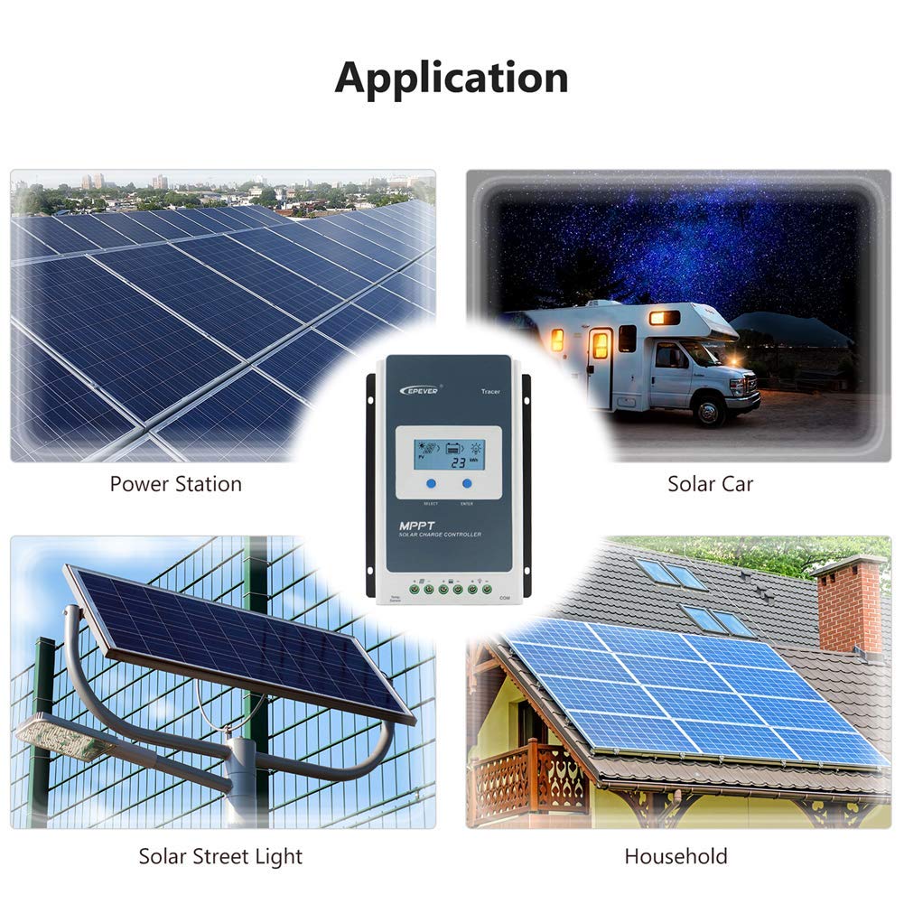
Figure 8.1: Controller Dimensions. This image provides the approximate length, width, height, and weight of the Tracer1210AN controller.
9. Application Examples
The EPEVER Tracer1210AN MPPT solar charge controller is suitable for a variety of off-grid solar applications.
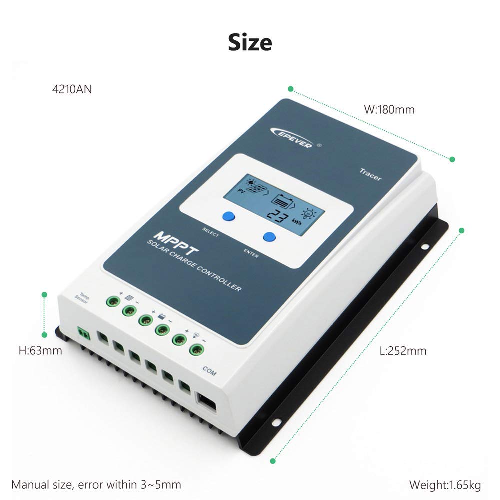
Figure 9.1: Typical Applications. This image illustrates common uses for the solar charge controller, including power stations, solar cars (RVs), solar street lights, and household solar systems.
- Power Stations: Small-scale off-grid power systems.
- Solar Cars/RVs: Charging batteries in recreational vehicles.
- Solar Street Lights: Managing power for autonomous lighting systems.
- Household Systems: Residential off-grid or backup power solutions.
10. Warranty and Support
EPEVER products are designed for reliability and performance.
10.1 Warranty Information
Please refer to the warranty card included with your product for specific warranty terms and conditions. Generally, EPEVER offers a limited warranty against defects in materials and workmanship. Keep your purchase receipt as proof of purchase.
10.2 Customer Support
For technical assistance, troubleshooting, or warranty claims, please contact EPEVER customer support or the authorized dealer from whom you purchased the product. You may also find helpful resources and FAQs on the official EPEVER website.
Note: When contacting support, please have your product model (Tracer1210AN) and serial number ready.


