1. Introduction and Overview
The EPEVER Tracer3210AN is a 30A Maximum Power Point Tracking (MPPT) solar charge controller designed for 12V/24V automatic system voltage detection. It features a maximum PV input voltage of 100V and negative grounding. This controller is equipped with an MT50 remote meter, a temperature sensor (RTS), and an RS485 PC communication cable for comprehensive monitoring and control.
This manual provides detailed instructions for the safe and efficient installation, operation, and maintenance of your Tracer3210AN solar charge controller.
2. Product Features
- Advanced MPPT Technology: Ensures high tracking efficiency (over 99.5%) for optimal solar energy harvesting.
- Automatic System Voltage: Automatically detects 12V or 24V battery systems.
- High PV Input: Supports maximum PV input voltage up to 100V.
- Negative Grounding: Common negative grounding design for system compatibility.
- Versatile Battery Compatibility: Supports Sealed, Gel, Flooded, Lithium, and user-defined battery types.
- Built-in LCD Display: Provides real-time display of key charging parameters.
- Multiple Communication Options: Includes RS-485 interface for PC software, mobile app connectivity (via optional accessories), and MT50 remote meter.
- USB Output: Dual USB ports (5V Max: 2.2A) for charging external devices.
- Current Limiting Function: Allows for future expansion of solar panels without overloading.
- Robust Design: Features aluminum alloy material for efficient heat dissipation.
3. Components Overview
The EPEVER Tracer3210AN kit includes the following components:
- Tracer3210AN MPPT Solar Charge Controller
- MT50 Remote Meter
- Remote Temperature Sensor (RTS)
- PC Communication Cable (RS485 to USB)
- Mounting Screws and Wall Plugs
- User Manual


4. Setup and Installation
Proper installation is crucial for the safe and efficient operation of your solar charge controller. Please follow these steps carefully.
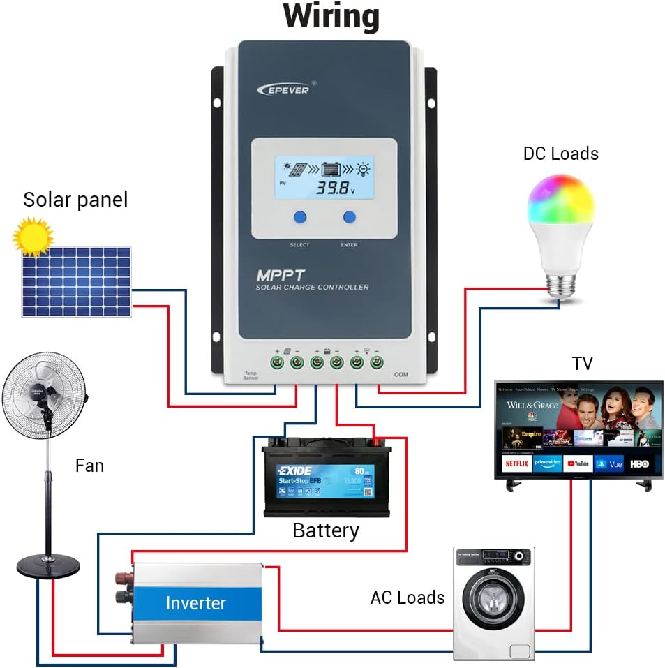
4.1 Wiring Instructions
Connection Order: Always connect the battery first, then the solar panel, and finally the load.
Disconnection Order: Disconnect the solar panel first, then the load, and finally the battery.
- Connect the battery to the controller's battery terminals (BAT+ and BAT-).
- Connect the solar panel to the controller's PV terminals (PV+ and PV-).
- Connect the load to the controller's load terminals (LOAD+ and LOAD-).
- Connect the Remote Temperature Sensor (RTS) to the designated RTS port.
- Connect the MT50 Remote Meter or PC Communication Cable to the RS485 port as needed.

4.2 Module Installation (if applicable)
The Tracer3210AN controller supports various interface modules for enhanced functionality. To change or install modules:
- Pry the cover of the controller off using a screwdriver.
- Insert the desired module (e.g., Display Standard 2 Modules (DS2), USB COM Slave (UCS)) into the designated slot.
- Replace the cover.
5. Operating Instructions
5.1 LCD Display and Button Functions
The controller features an LCD display and buttons for monitoring and setting parameters.
- PV Browsing Interface: Press the button to view PV data. Hold for 5 seconds to set data.
- BATT Browsing Interface: Press the button to view battery data. Hold for 5 seconds to set battery type, capacity, and temperature.
- Load Browsing Interface: Press the button to view load data. Hold for 5 seconds to set load working mode.
- Setting Interface: Press the button to enter settings. Hold for 5 seconds to set parameters.
5.2 Setting Battery Type
To ensure proper charging, set the correct battery type:
- Press the SET button for the setting interface.
- Press the BATT button and hold for 5 seconds to enter the battery type interface.
- Press the PV+ or LOAD- buttons to choose the battery type (e.g., Sealed, GEL, FLD, LiFePO4, Li(NiCoMn)O2, USE).
- Press the SET button to confirm the battery type.
CAUTION: When the default battery type is selected, the battery voltage control parameters will be set by default and cannot be changed. To change these parameters, select "User" battery type.
5.3 Setting Load Working Mode
The controller offers various load working modes:
- Manual Control Mode (default): Press the button to open/close the load.
- Light ON/OFF: Load turns on/off based on light conditions.
- Light ON + Timer: Load turns on based on light and stays on for a set duration.
- Time Control: Load operates according to a programmed schedule.
Refer to the MT50 remote meter or PC software for detailed configuration of load working modes.
6. Maintenance
To ensure optimal performance and longevity of your EPEVER Tracer3210AN solar charge controller, regular maintenance is recommended:
- Inspect Connections: Periodically check all wiring connections for tightness and corrosion. Loose connections can cause overheating and damage.
- Clean Controller: Keep the controller clean and free from dust and debris. Ensure the heat sink fins are not obstructed to maintain proper cooling.
- Monitor Performance: Regularly check the LCD display or connected remote meter/app for normal operating parameters (PV voltage, battery voltage, charging current).
- Battery Inspection: Inspect battery terminals for corrosion and ensure the battery is in good condition. For flooded batteries, check electrolyte levels.
- Environmental Check: Ensure the installation environment is within the specified temperature and humidity ranges.
7. Troubleshooting
If you encounter issues with your Tracer3210AN controller, consider the following common troubleshooting steps:
- No Display/Power: Check battery connections and ensure the battery voltage is within the operating range. Verify fuses are intact.
- No Charging: Confirm solar panel connections are secure and receiving adequate sunlight. Check PV voltage on the display. Ensure the battery type is correctly set.
- Load Not Working: Verify load connections. Check the load working mode settings. Ensure the battery has sufficient charge.
- Error Codes: Refer to the full user manual for specific error codes displayed on the LCD or MT50 remote meter.
For persistent issues, contact EPEVER customer support or consult a qualified technician.
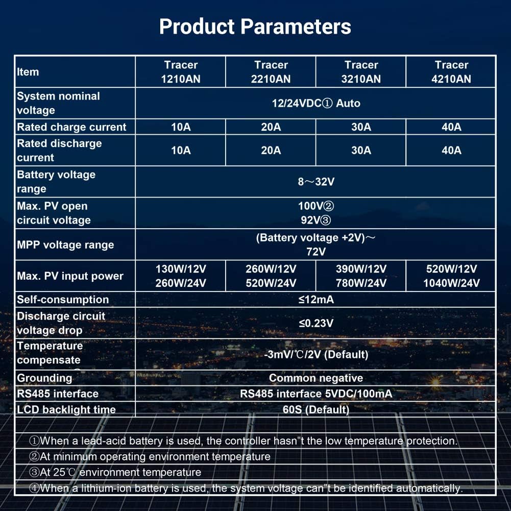
8. Technical Specifications
Below are the detailed specifications for the Tracer3210AN model:
| Item | Tracer 3210AN |
|---|---|
| System nominal voltage | 12/24VDC Auto |
| Rated charge current | 30A |
| Rated discharge current | 30A |
| Battery voltage range | 8~32V |
| Max. PV open circuit voltage | 100V |
| MPP voltage range | (Battery voltage +2V)~72V |
| Max. PV input power | 390W/12V, 780W/24V |
| Self-consumption | ≤12mA |
| Discharge circuit voltage drop | ≤0.23V |
| Temperature compensate coefficient | -3mV/°C/2V (Default) |
| Grounding | Common negative |
| RS485 interface | 5VDC/100mA |
| LCD backlight time | 60S (Default) |
| Storage temperature range | -20℃ ~ +70℃ |
| Relative humidity | ≤95%, N.C. |
| Enclosure | IP30 |
| Mounting hole size | Φ5mm |
Note: When a lead-acid battery is used, the controller has no low temperature protection. Max PV open circuit voltage is at minimum operating environment temperature. At 25℃ environment temperature. When a lithium-ion battery is used, the system voltage cannot be identified automatically.
9. Connectivity Options
The Tracer3210AN controller offers various connectivity options for monitoring and control:
- MT50 Remote Meter: Displays operating data and fault information. Easy to operate with a numeric display.
- PC Software: Connect via USB to RS485 cable (CC-USB-RS485-150U) for monitoring and parameter modification using Solar Station PC software.
- Mobile App: Connect via OTG cable (OTG-12CM) or optional WiFi/Bluetooth adapters (eBox-WiFi-01, eBox-BLE-01) for real-time monitoring and parameter modification via mobile app.
- Logger: eLOG01 logger can record operating data of the controller for later review.
10. Warranty and Support
For warranty information, technical support, or service inquiries, please refer to the warranty card included in your product packaging or visit the official EPEVER website. Ensure you have your product model and serial number available when contacting support.
For additional resources and FAQs, you may visit the EPEVER Store on Amazon.


