Introduction
This manual provides detailed instructions for the installation, operation, maintenance, and troubleshooting of your EPEVER Tracer 5415AN 50A MPPT Solar Charge Controller. Please read this manual thoroughly before installation and use to ensure optimal performance and safety.

Image: Front view of the EPEVER Tracer 5415AN 50A MPPT Solar Charge Controller, showing the LCD display and control buttons.
Product Features
The EPEVER Tracer 5415AN controller incorporates advanced technology and design for efficient solar power management:
- Advanced MPPT technology with ultra-fast tracking speed, achieving tracking efficiency of no less than 99.5%.
- Utilizes high-quality components from ST and Infineon for enhanced product longevity and reliability.
- Adaptive three-stage charging mode based on a digital control circuit to prolong battery life and improve system performance.
- Load, utility, or generator auto-control relays facilitate easy integration into hybrid power systems.
- Comprehensive electronic protections including overcharging, over-discharging, and PV reverse polarity protection for safe and reliable operation.
- Features battery temperature compensation, real-time energy recording, statistical functions, and automatic over-temperature power reduction.
- Designed for 100% full load operation within its specified working environment temperature range for both charging and discharging.
- Wide maximum power point operating voltage range improves photovoltaic module utilization.
- Rated charging power and charging current double automatic limiting function.
- Supports four charging options: Sealed, Gel, Flooded, and User-defined.
- Isolated RS485 interface with standard MODBUS communication protocol and 5V power supply for application expansion.
- Supports up to 8 units in parallel for system expansion and diverse monitoring requirements, suitable for solar RVs, household systems, and field monitoring.

Image: Detailed diagram identifying the various components and indicators on the EPEVER Tracer 5415AN controller.
Key Components: 1. Charging LED indicator, 2. SELECT button, 3. Fuse, 4. Grounding Terminal, 5. Fault LED indicator, 6. LCD, 7. ENTER button, 8. Load control relay, 9. RBVS Port, 10. Utility/Generator relay ON, 11. RS485 port (5VDC/200mA), 12. RTS Port, 13. Generator and load relay enable, 14. PV reverse polarity alarm indicator, 15. Utility/Generator relay OFF, 16. PV Terminals, 17. Battery Terminals.
Setup and Installation
Proper installation is crucial for the safe and efficient operation of your solar charge controller. Please follow these guidelines carefully.
Safety Precautions
- Ensure all power sources are disconnected before installation or maintenance.
- Install the controller in a well-ventilated area, away from flammable gases and liquids.
- Use appropriate tools and wear protective gear.
- Connect the battery first, then the solar panel, and finally the load. Disconnect in reverse order.
Mounting the Controller
Mount the controller vertically on a wall or suitable surface, ensuring adequate clearance around the unit for heat dissipation. The controller features an aluminum alloy material for good heat dissipation.
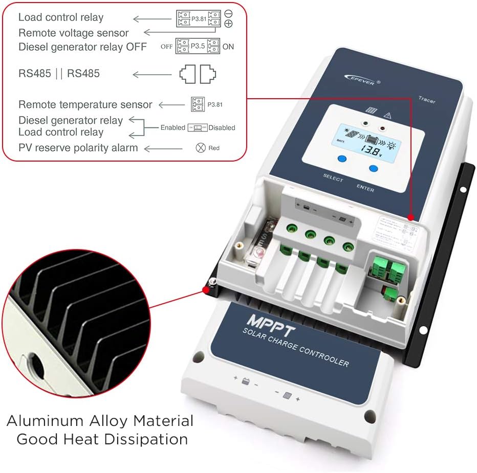
Image: Internal view of the EPEVER Tracer 5415AN, highlighting the aluminum alloy heat sink for efficient heat dissipation and various connection ports.
Wiring Diagram
Refer to the following diagram for correct wiring connections. Ensure all connections are secure and polarity is correct.

Image: A comprehensive wiring diagram illustrating the connection of solar panels, batteries, inverter, and various loads (TV, computer, fan, washing machine, speakers) to the EPEVER Tracer 5415AN solar charge controller.
- Battery Connection: Connect the battery to the controller's battery terminals (17) first. Ensure correct polarity (+ to + and - to -).
- Solar Panel Connection: Connect the solar panel to the controller's PV terminals (16). Verify correct polarity.
- Load Connection: Connect your DC loads to the controller's load terminals.
- Grounding: Connect the grounding terminal (4) to earth ground.
- Optional Connections: Connect remote voltage sensor, remote temperature sensor (RTS Port 12), RS485 communication (11), and relay controls as needed.

Image: Close-up view of the EPEVER Tracer 5415AN's internal connections, showing labels for Load control relay, Remote voltage sensor, Diesel generator relay OFF/ON, RS485, Remote temperature sensor, PV reverse polarity alarm, and the internal fuse.
Operating Instructions
Once installed, the controller will automatically begin operation. The LCD display (6) provides real-time system status.
LCD Display and Buttons
The LCD displays various parameters such as battery voltage, charging current, PV voltage, and load status. Use the SELECT (2) and ENTER (7) buttons to navigate through menus and adjust settings.
Charging Process
The controller uses an adaptive three-stage charging algorithm:
- Bulk Charge: Maximum current is delivered to the battery until its voltage rises to the absorption voltage.
- Absorption Charge: Voltage is held constant, and current gradually decreases as the battery becomes fully charged.
- Float Charge: Voltage is reduced to a lower level to maintain the battery at full charge and compensate for self-discharge.
Battery Type Settings
The controller supports Sealed, Gel, Flooded, and User-defined battery types. It is essential to select the correct battery type in the settings to ensure proper charging and prolong battery life. Refer to the detailed manual for specific parameter adjustments for user-defined settings.
Maintenance
Regular maintenance ensures the longevity and optimal performance of your EPEVER Tracer 5415AN controller.
- Check Connections: Periodically inspect all wiring connections for tightness and corrosion. Loose connections can cause overheating and damage.
- Clean the Controller: Keep the controller clean and free from dust and debris. Ensure ventilation openings are not obstructed.
- Inspect for Damage: Check for any physical damage to the casing, cables, or terminals.
- Monitor Performance: Regularly check the LCD display for normal operation and any fault indicators.
Troubleshooting
This section addresses common issues you might encounter with your solar charge controller.
| Problem | Possible Cause | Solution |
|---|---|---|
| No display or indicators | Battery not connected or low voltage; reverse polarity. | Check battery connections and voltage. Ensure correct polarity. |
| No charging from PV | PV panels not connected; low sunlight; PV reverse polarity; PV open circuit voltage too low/high. | Check PV connections and polarity. Verify sunlight conditions. Ensure PV voltage is within specifications. |
| Load not working | Load disconnected; overcurrent; short circuit; low battery voltage. | Check load connections. Reduce load. Check for short circuits. Charge battery. |
| Inaccurate voltage readings (especially with LiFePo4) | Internal voltage feedback variations during high current flow. | While the controller has remote voltage sensing, some variations may occur. Ensure remote voltage feedback is correctly installed. For critical applications, external monitoring may be required. Adjust absorption voltage settings carefully for LiFePo4 batteries, considering potential offsets. |
| Over-temperature warning | Insufficient ventilation; high ambient temperature; excessive load. | Ensure adequate airflow around the controller. Reduce load if ambient temperature is high. |
For issues not listed here, or if troubleshooting steps do not resolve the problem, please contact customer support.
Specifications
The following table provides detailed technical specifications for the EPEVER Tracer 5415AN 50A MPPT Solar Charge Controller.

Image: A table detailing the technical parameters for Tracer5415AN, Tracer6415AN, Tracer8415AN, and Tracer10415AN models, including nominal system voltage, battery input voltage range, battery types, rated charge current, rated charge power, max PV open circuit voltage, MPP voltage range, tracking efficiency, max conversion efficiency, full load efficiency, temperature compensation coefficient, self-consumption, grounding, RS485 interface, relay, LCD backlight time, ambient temperature range, mounting hole size, and enclosure rating.
General Specifications (Tracer 5415AN)
- Nominal System Voltage: 12V/24V/36V/48V DC Auto
- Battery Input Voltage Range: 8V ~ 68V
- Battery Type: Sealed (Default), Gel, Flooded, User
- Rated Charge Current: 50A
- Rated Charge Power: 625W/12V, 1250W/24V, 1875W/36V, 2500W/48V
- Max. PV Open Circuit Voltage: 150V
- MPP Voltage Range: (Battery Voltage +2V) ~ 108V
- Tracking Efficiency: ≥99.5%
- Max. Conversion Efficiency: 98.30%
- Full Load Efficiency: 97.80%
- Temperature Compensate Coefficient: -3mV/°C/2V (Default)
- Self-Consumption: 98mA/12V, 60mA/24V, 50mA/36V, 46mA/48V
- Grounding: Common negative grounding
- RS485 Interface: RS485 (RJ45)
- Ambient Temperature Range: -25°C ~ +60°C (Derate above 45°C)
- Enclosure: IP20
- Item Weight: 8.69 pounds
- Package Dimensions: 13.39 x 10.87 x 7.32 inches
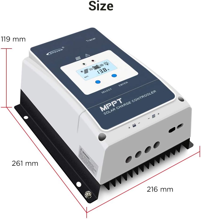
Image: Diagram showing the physical dimensions of the EPEVER Tracer 5415AN controller: 119 mm height, 261 mm length, and 216 mm width.
Applications
The EPEVER Tracer 5415AN MPPT Solar Charge Controller is versatile and suitable for a variety of solar power applications, including:
- Off-grid residential solar systems
- Solar RV and marine applications
- Remote monitoring stations
- Solar street lighting
- Small commercial solar installations

Image: Collage showing different applications of the EPEVER solar charge controller, including rooftop solar panels, solar RVs, solar street lights, and residential solar setups.
Warranty and Support
For warranty information, technical support, or service inquiries, please contact the seller or manufacturer directly. Refer to your purchase documentation for specific warranty terms and contact details.
The manufacturer, EPEVER, and seller, iSunergy, are committed to providing reliable products and customer assistance.
For additional resources and product information, you may visit the iSunergy Brand Store on Amazon.


