
1. Product Overview
The Walfront STC-100A is a versatile digital temperature controller designed for precise temperature management in various applications, including refrigerating and heating systems. It features a clear digital display, intuitive controls, and robust functionality for maintaining desired temperature ranges.
Key Features:
- Refrigerating & Heating Mode: Supports both cooling and heating operations, offering flexibility for different environmental control needs.
- User-Friendly Operation: Simple and convenient temperature setting with a limited range for ease of use.
- Advanced Functions: Includes temperature correction, sensor failure alarm, and control output delay for enhanced reliability and precision.
- Accurate Temperature Control: Maintains temperature based on set value and return difference, ensuring stable conditions.
- Durable Construction: Manufactured from high-quality ABS material for long-term durability and performance.

Figure 1.1: Front view of the Walfront STC-100A Digital Temperature Controller, showing the digital display and control buttons.
2. Important Safety Information
Please read and understand all safety instructions before installing or operating the STC-100A temperature controller. Failure to follow these instructions may result in electric shock, fire, or serious injury.
- Electrical Hazard: This device operates on 220VAC. All wiring and installation should be performed by a qualified electrician or knowledgeable individual.
- Correct Wiring: Carefully distinguish between the relay interface, sensor wiring, and power supply wiring. Incorrect connections can damage the device or connected equipment.
- Wire Separation: Maintain a proper distance between the sensor wire and the power supply wire to prevent interference and ensure accurate readings.
- Verify Voltage: Always check that the supply voltage is correct (220VAC) before electrifying the unit.
- Environmental Conditions: Do not expose the controller to excessive moisture, dust, or extreme temperatures outside its specified operating range (0℃-60℃, Relative Humidity: No more than 85% non-condensing).
- Disconnection: Disconnect power before performing any maintenance or wiring changes.

Figure 2.1: Rear view of the controller with the wiring diagram and important caution notes regarding installation.
3. Package Contents
Upon opening the package, please verify that all components are present and undamaged:
- 1 x Walfront STC-100A Temperature Controller
- 1 x Temperature Sensor Cable
- 1 x Instruction Manual (this document)
4. Technical Specifications
| Parameter | Value |
|---|---|
| Model | STC-100A |
| Material | ABS |
| Power Supply Voltage | 220VAC ±10%, 50/60Hz |
| Power Consumption | Less than 3W |
| Temperature Measurement Range | -50℃ to 99℃ |
| Resolution | 1℃ |
| Accuracy | ±1℃ |
| Output Relay Capacity | 10A/220VAC |
| Operating Environment Temperature | 0℃ to 60℃ |
| Relative Humidity | No more than 85% (non-condensing) |
| Mounting Hole Size | Approx. 71 x 29 mm / 2.8 x 1.1 in |
| Product Dimensions | 2.76 x 2.36 x 1.38 inches |
| Item Weight | 7 ounces (0.2 Kilograms) |
5. Installation and Wiring
The STC-100A is designed for panel mounting. Ensure proper ventilation around the unit.
5.1 Mounting
- Cut a rectangular opening in your panel with dimensions of approximately 71mm x 29mm (2.8 x 1.1 inches).
- Insert the controller into the opening from the front.
- Secure the controller using the orange mounting clips on the sides. Push them inwards to lock the controller in place.

Figure 5.1: Side view illustrating the mounting clips for panel installation.
5.2 Wiring Instructions
Refer to the wiring diagram on the back of the unit and Figure 5.2 below. Ensure all connections are secure and insulated.
- Power Supply (220VAC): Connect your 220VAC power source to terminals 6 and 7. Ensure correct polarity if applicable, though AC typically does not have strict polarity for power input.
- Temperature Sensor: Connect the temperature sensor cable to terminals 4 and 5. The sensor is non-polar, so connection order does not matter. Keep this wire separate from power wires.
- Output Relay (10A/220VAC):
- Terminal 1: Common (COM) for the relay output.
- Terminal 2: Normally Closed (NC) contact.
- Terminal 3: Normally Open (NO) contact.
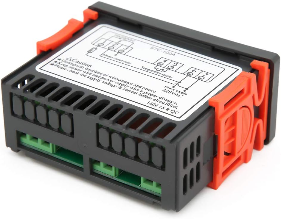
Figure 5.2: Rear view showing the terminal block for power, sensor, and relay connections.
6. Operating Instructions
The STC-100A features a digital display and three buttons: Up (↑), Down (↓), and Set (SET).
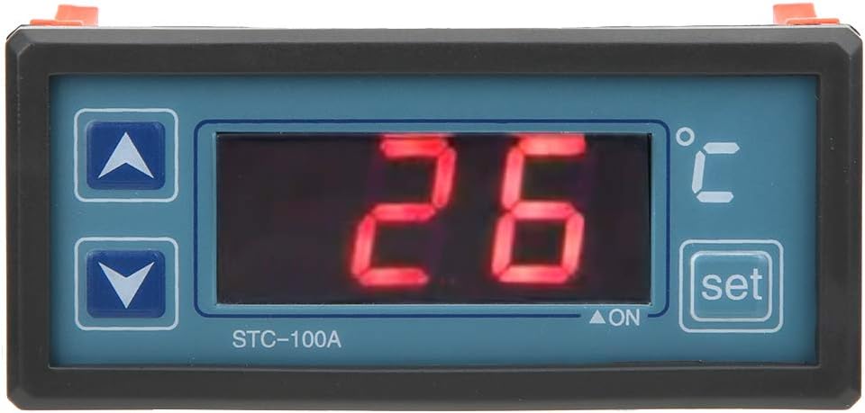
Figure 6.1: Close-up of the control panel showing the display and buttons.
6.1 Setting the Temperature
- Press the SET button once. The display will flash, indicating that you are in temperature setting mode.
- Use the ↑ (Up) and ↓ (Down) buttons to adjust the desired temperature set point.
- Press the SET button again to confirm the setting and exit the setting mode. The display will return to showing the current temperature.
6.2 Understanding Control Modes (Refrigerating/Heating)
The STC-100A automatically switches between refrigerating and heating modes based on the set temperature and the current temperature, in conjunction with a configurable "return difference" (hysteresis). This ensures stable temperature control without rapid cycling.
For example, if set to 25°C with a 2°C return difference:
- Heating Mode: If the current temperature drops below 23°C (25°C - 2°C), the heating output will activate. It will deactivate when the temperature reaches 25°C.
- Refrigerating Mode: If the current temperature rises above 27°C (25°C + 2°C), the refrigerating output will activate. It will deactivate when the temperature drops to 25°C.
Note: The specific parameter for setting the return difference (hysteresis) is typically accessed through a hidden menu or a combination of button presses. Refer to the detailed wiring diagram on the unit for advanced parameter settings if available.
6.3 Advanced Functions
- Temperature Correction: Allows for fine-tuning the temperature reading to match a known accurate thermometer. This compensates for any sensor inaccuracies.
- Sensor Failure Alarm: The unit will display an error code or alarm if the temperature sensor is disconnected or faulty.
- Control Output Delay: This feature prevents rapid cycling of the compressor or heating element, extending the lifespan of connected equipment. It introduces a delay before the output activates after a temperature change.
Detailed instructions for accessing and adjusting these advanced parameters are usually found in the full technical manual or by consulting the manufacturer's support resources.
7. Maintenance
The Walfront STC-100A is designed for minimal maintenance. Follow these guidelines to ensure its longevity and proper operation:
- Cleaning: Periodically wipe the display and casing with a soft, dry cloth. Do not use abrasive cleaners or solvents. Ensure no liquid enters the unit.
- Ventilation: Ensure that the ventilation slots on the sides of the unit are not obstructed to prevent overheating.
- Wiring Inspection: Annually inspect all wiring connections for tightness and signs of wear or corrosion.
- Sensor Care: Keep the temperature sensor clean and free from debris. Ensure it is properly positioned in the area where temperature needs to be measured.
8. Troubleshooting
This section provides solutions to common issues you might encounter with your STC-100A temperature controller.
| Problem | Possible Cause | Solution |
|---|---|---|
| Display is blank / Unit not powering on | No power supply; Incorrect wiring; Blown fuse (external) | Check power connections (terminals 6 & 7). Verify supply voltage. Check external fuse or circuit breaker. |
| "EE" or "HH" error on display | Temperature sensor fault (open circuit, short circuit, or out of range) | Check sensor wiring (terminals 4 & 5) for loose connections or damage. Replace sensor if faulty. Ensure temperature is within -50℃ to 99℃. |
| Temperature reading is inaccurate | Sensor not properly placed; Need for temperature correction | Relocate sensor to a representative area. Use the temperature correction function (refer to advanced settings). |
| Output (heater/cooler) not activating | Incorrect temperature set point; Hysteresis setting too wide; Output relay wiring issue; Control output delay active | Verify set temperature. Check relay connections (terminals 1, 2, 3). Wait for delay period to expire. Consult advanced settings for hysteresis. |
| Output cycles too frequently | Hysteresis (return difference) set too narrow | Increase the hysteresis value in the advanced settings to prevent rapid cycling. |
If the problem persists after attempting these solutions, please contact Walfront customer support or a qualified technician.
9. Warranty and Support
For specific warranty terms and conditions, please refer to the documentation provided at the time of purchase or contact your retailer. Walfront products are typically covered by a manufacturer's warranty against defects in materials and workmanship.
For technical support, troubleshooting assistance beyond this manual, or inquiries about replacement parts, please visit the official Walfront website or contact their customer service department through the contact information provided with your purchase.
You can also visit the Walfront store on Amazon for more information: Walfront Amazon Store