
1. Product Overview
The CO-Z 400W Sliding Gate Opener Kit (Model SL1500AC) is designed to automate sliding gates weighing up to 1000 kg and with a maximum length of 12 meters. This kit provides convenience and security for various applications, including residential, commercial, and agricultural properties. It features a powerful 400W DC motor, durable construction, advanced safety features like infrared photocell sensors, and an adjustable automatic closing function.

Image 1.1: CO-Z 400W Sliding Gate Opener Kit (Model SL1500AC)
Key Features
- Powerful 400W Motor: Capable of handling gates up to 1000 kg and 12 meters in length.
- Durable Construction: Features an aluminum base and copper worm gear for extended lifespan.
- Enhanced Security: RF Hopping Code technology prevents unauthorized remote access.
- Infrared Photocell Sensors: Automatically reopens the gate if an obstruction is detected during closing.
- Adjustable Automatic Closing: Configurable closing times (15, 30, 45 seconds) for added convenience.
- Wide Application: Suitable for various gate types and environments.

Image 1.2: Overview of key features including power, weight capacity, remote range, and weather resistance.
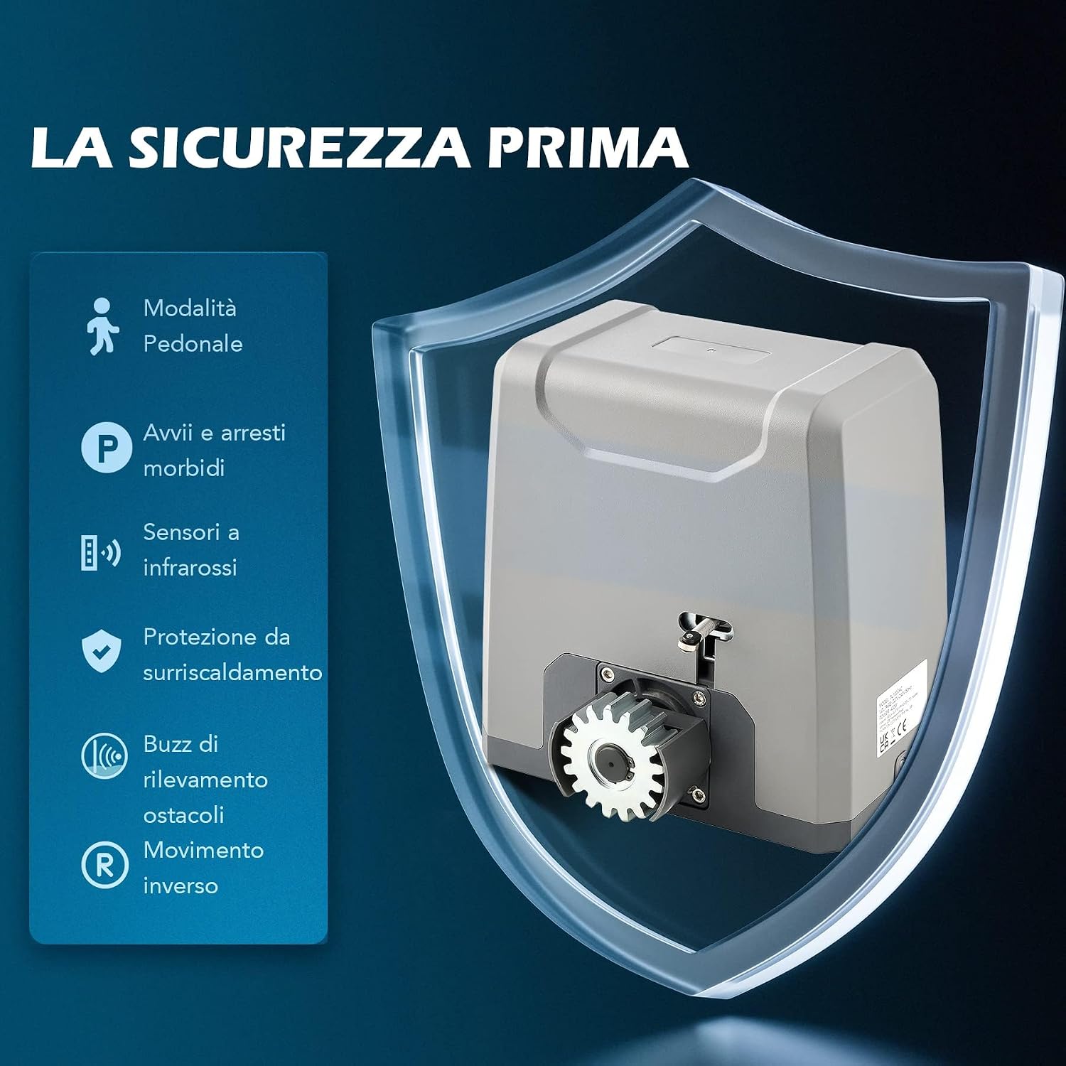
Image 1.3: Safety features such as pedestrian mode, soft start/stop, infrared sensors, overheat protection, obstacle detection, and reverse movement.

Image 1.4: Customizable settings including adjustable gate speed, operating time (10-90 sec), optional left/right opening, and automatic closing timer (12/24/36 sec).
2. Safety Information
Read and understand all safety warnings and instructions before installing and operating this product. Failure to follow these instructions may result in serious injury or property damage. Keep this manual for future reference.
General Safety Warnings
- Always ensure the gate area is clear of people, pets, and objects before operating the gate.
- Do not allow children to play near the gate or with the remote control.
- Keep remote controls out of reach of children.
- Never attempt to stop a moving gate with your hands or any part of your body.
- In case of power failure, use the manual release key to operate the gate.
- Regularly inspect the gate opener, gate, and all accessories for signs of wear, damage, or misalignment.
- Installation and repairs should only be performed by qualified personnel.
- Ensure all electrical connections comply with local electrical codes and regulations.
- Disconnect power to the gate opener before performing any maintenance or repairs.
3. Setup & Installation
This section provides detailed instructions for installing your CO-Z Sliding Gate Opener Kit. It is recommended to watch the full installation video for a visual guide.
Video 3.1: CO-Z Sliding Gate Opener Installation Guide. This video demonstrates the step-by-step process for installing the gate opener, including rack, motor, wiring, limit switches, and IR sensors.
3.1. Package Contents
Before starting, verify that all components are present in the package:

Image 3.1: Detailed view of all components included in the CO-Z Sliding Gate Opener Kit.
3.2. Rack Installation
- Prepare Components: Gather all necessary rack components, including the gear racks, mounting plates, and self-tapping screws.
- Align Rack to Pinion: Position the first gear rack against the gate, aligning it with the motor's pinion gear. Ensure a small gap (approximately 1-2mm) between the rack and the pinion to allow for smooth movement.
- Mark Installation Points: While holding the rack in place, mark the drilling points on the gate for securing the rack.
- Secure Rack: Fix the rack to the gate using the provided self-tapping screws and mounting plates.
- Repeat for Remaining Racks: Continue the process for all remaining rack sections, ensuring they are properly aligned and secured along the entire length of the gate.

Image 3.2: Close-up of the rack aligned with the motor's pinion gear.
3.3. Motor Installation
- Position Motor: Place the motor unit onto its mounting base, ensuring it is level and securely positioned.
- Tighten Bolts: Secure the motor to the base by tightening all bolts.
- Verify Smooth Sliding: Unlock the gate opener using the provided key to disengage the motor. Manually move the gate back and forth to ensure it slides smoothly without obstruction.

Image 3.3: The gate opener motor installed at the base of a sliding gate.
3.4. Electrical Wiring
- Remove Cover: Carefully remove the cover of the electronic control board.
- Route Cables: Pass the main power cable and any accessory cables (e.g., for IR sensors) through the designated cable glands.
- Make Connections: Connect the wires to the appropriate terminals on the control board as indicated in the wiring diagram (refer to the product manual for a detailed diagram). Ensure all connections are secure.

Image 3.4: Close-up of the electronic control board with wiring terminals.
3.5. Limit Switch Installation
Install the left and right limit switches to define the gate's open and closed positions.
- Mount Left Limit Switch: Attach the left limit switch bracket to the gate, ensuring it aligns with the motor's limit switch mechanism when the gate is in its fully open position. Secure it with screws.
- Mount Right Limit Switch: Attach the right limit switch bracket to the gate, ensuring it aligns with the motor's limit switch mechanism when the gate is in its fully closed position. Secure it with screws.
- Verify Operation: Manually move the gate to its open and closed positions to confirm that the limit switches are correctly engaged and stop the gate at the desired points.
3.6. Infrared Sensor Installation
Install the infrared photocell sensors to enhance safety by detecting obstructions.
- Connect Receiver: Connect the receiver sensor's V+ wire to 24V, V- and COM wires to GND, and NC wire to IR on the control board.
- Connect Transmitter: Connect the transmitter sensor's V+ wire to 24V and V- wire to GND on the control board.
- Intertwine Wires: Intertwine the V+ transmitter wire with the V+ receiver wire, and the V- transmitter wire with the V- receiver wire and COM. Connect all signal wires to the signal terminal and reconnect to the circuit board.
- Position Sensors: Mount both the transmitter and receiver sensors at the same height on opposite sides of the gate opening, ensuring they face each other directly.
- Test Sensors: Obstruct the path between the sensors. If the alarm light activates and indicator No. 8 on the control board turns off, the IR sensors are correctly configured.
- Install Covers: Once confirmed, install the covers for both infrared sensors.
4. Operation
This section describes how to operate your CO-Z Sliding Gate Opener using the remote control and its various functions.
4.1. Remote Control Pairing
To pair your remote control with the gate opener:
- Access Control Board: Ensure the control board cover is removed.
- Initiate Learning Mode: Press and hold the 'LEARN' button on the control board until the 'LEARN' indicator light turns on.
- Pair Remote: While the 'LEARN' light is on, press the top button of your remote control twice. The 'LEARN' light will flash to confirm successful pairing.
4.2. Basic Gate Operation
- Open/Close: Press the paired button on your remote control to open or close the gate.
- Stop: Press the same button again while the gate is in motion to stop it.
- Pedestrian Mode: If configured, a separate button on the remote may activate pedestrian mode, opening the gate partially for foot traffic.
4.3. Automatic Closing Function
The gate opener can be configured to close automatically after a set period. Refer to the control board settings in your detailed manual for adjusting the automatic closing time (15, 30, or 45 seconds).
5. Maintenance
Regular maintenance ensures the longevity and optimal performance of your gate opener.
- Monthly Inspection: Check the gate and opener for any loose bolts, worn parts, or obstructions. Ensure the gate slides freely.
- Clean Sensors: Keep the infrared photocell sensors clean and free from dirt, dust, or spiderwebs to ensure proper operation.
- Lubrication: Periodically lubricate the gate's moving parts (e.g., wheels, hinges) as recommended by the gate manufacturer. Do not lubricate the gear rack or pinion.
- Power Disconnection: Always disconnect power to the unit before performing any maintenance or cleaning.
6. Troubleshooting
This section addresses common issues you might encounter with your gate opener.
| Problem | Possible Cause | Solution |
|---|---|---|
| Gate does not respond to remote. | Dead remote battery, remote not paired, power issue. | Replace remote battery. Re-pair remote (Section 4.1). Check power supply to the unit. |
| Gate stops or reverses unexpectedly. | Obstruction detected by IR sensors, gate friction, faulty sensor. | Clear obstructions from gate path. Clean IR sensors. Check gate for smooth movement. Inspect sensor wiring. |
| Gate does not fully open or close. | Limit switches incorrectly set, gate obstruction. | Adjust limit switch positions (Section 3.5). Check for physical obstructions. |
| Motor makes noise but gate does not move. | Motor disengaged, pinion not engaging rack, motor fault. | Ensure motor is engaged (manual release lever). Check rack and pinion alignment. Contact support if motor fault is suspected. |
7. Specifications
Below are the technical specifications for the CO-Z 400W Sliding Gate Opener Kit SL1500AC:

Image 7.1: Technical specifications table for the CO-Z Sliding Gate Opener.
| Feature | Detail |
|---|---|
| Brand | CO-Z |
| Model Number | SL1500AC |
| Power Input | 220-240V 50Hz |
| Rated Power | 400W |
| Max. Gate Weight | 1000 kg |
| Max. Gate Length | 12 m |
| Output Torque | 22 Nm |
| Gate Speed Range | 11-13 m/min |
| Remote Range | 30 m |
| Ingress Protection (IP) Rating | IP44, IP54 |
| Operating Temperature | -20°C to 70°C |
| Material | Steel Alloy, Aluminum |
| Rack Material | Nylon (Note: Steel racks are required for gates over 4m wide) |
| Product Dimensions (L x W x H) | 25L x 23W x 28H cm |
| Item Weight | 18 kg |
| Included Components | Gate Opener Motor, 2 Remote Controls, Infrared Sensors, 4m Gear Rack, Installation Hardware |

Image 7.2: Dimensions of the CO-Z Sliding Gate Opener and a section of the gear rack.
8. Warranty & Support
For warranty information, please refer to the specific terms and conditions provided at the time of purchase or contact your retailer. For technical support, troubleshooting assistance, or to inquire about replacement parts, please contact CO-Z customer service through the details provided on the product packaging or the official CO-Z website.


