1. Introduction
This manual provides detailed instructions for the installation, operation, and troubleshooting of the Walfront FV-200Hz5V Frequency to Voltage Conversion Module. Please read this manual carefully before use to ensure proper functionality and safety.
The FV-200Hz5V module is designed to convert an input frequency signal ranging from 0-200Hz into a corresponding 0-5V analog voltage output. This module is suitable for applications requiring an interface between PLCs, movement control cards, and frequency converters.

Image 1.1: Top view of the Walfront FV-200Hz5V Frequency to Voltage Converter Module, showing the green terminal block and various electronic components on the circuit board.
2. Setup
2.1 Power Supply Requirements
- The input power supply voltage range is 12-30V DC.
- A power supply voltage of 15-24V DC is recommended for optimal performance.
- If using a 12V level input, the module requires at least a 15V DC power supply. A 12V DC power supply is not sufficient for the module itself in this configuration.
- For 24V level inputs, a 24V DC power supply is required.
2.2 Wiring Instructions
Connect the module according to the following pin assignments:

Image 2.1: Close-up view of the Walfront FV-200Hz5V module's terminal block, showing the labeled pins for power input, frequency input, and voltage output.
- 12-30V: Power input positive.
- GND: Power input negative (common ground wire).
- GND: Pulse frequency input negative (common ground wire).
- 0-10KHZ: Pulse frequency input positive.
- GND: Pulse frequency input negative (common ground wire).
- 0-10V: Analog 0-10V level output (Note: For FV-200Hz5V, this output range is 0-5V).
2.3 Important Precautions
- The multi-turn potentiometer on the board is used for fine-tuning the frequency-to-voltage conversion relationship. It is generally pre-calibrated at the factory and adjustment is not recommended unless necessary.
- The input signal is isolated by a diaphragm to enhance anti-interference capabilities.
- When used with a PLC, the module supports NPN type inputs. A ground wire must be connected.
- If an encoder is used as the frequency source, ensure the encoder rotates at a constant speed for more than 0.5 seconds for stable readings.
- The module's response time for frequency to voltage conversion is approximately 0.3-0.5 seconds.
3. Operating Instructions
3.1 Basic Functionality
The Walfront FV-200Hz5V module converts an input frequency signal (0-200Hz) into a proportional analog voltage output (0-5V). The output current is 5mA.

Image 3.1: The FV-200Hz5V module shown in an illustrative application, highlighting its use in converting interfaces between PLCs and frequency devices or movement control cards.
3.2 Calibration
The module is factory-calibrated. If a deviation in the frequency-to-voltage correspondence is observed, the blue multi-turn potentiometer (labeled 'W103' or similar) on the board can be adjusted. Use a small screwdriver to carefully turn the potentiometer until the desired output voltage is achieved for a given input frequency.
3.3 Linear Relationship
The conversion follows a linear relationship:
| Input Frequency | Output Voltage |
|---|---|
| 20 Hz | 0.5 V |
| 100 Hz | 2.5 V |
| 200 Hz | 5 V |
4. Troubleshooting
- Incorrect Voltage Output: If the output voltage is not as expected, first verify the input frequency signal. If a deviation persists, carefully adjust the blue potentiometer on the board.
- No Output or Unstable Output:
- Check the power supply voltage. Ensure it is within the 12-30V DC range and meets the minimum 15V DC requirement if a 12V level input is used.
- Verify all wiring connections are secure and correct according to Section 2.2.
- The module is sensitive to input waveform. It is designed for square wave inputs and may not function correctly with sine waves or signals with slow slew rates. If your signal has a lazy slew rate, consider using an NPN transistor to sharpen the edges of the square wave (collector to input, emitter to ground, base to signal input).
- Ensure the input frequency signal is stable and maintained for at least 0.5 seconds.
- Interference Issues: The module features input isolation to reduce interference. Ensure proper grounding and shielding in your system to minimize external noise.
- PLC Compatibility: If using with a PLC, confirm that the PLC output is NPN type and that a common ground wire is properly connected.
5. Specifications
| Feature | Specification |
|---|---|
| Item Type | Frequency To Voltage Conversion Module |
| Model | FV-200Hz5V |
| Function | Input 0-200Hz frequency converted to 0-5V analog output |
| Output Current | 5mA |
| Response Time | 0.3-0.5 seconds |
| Input Power Supply Voltage | 12-30V DC (Recommended: 15-24V DC) |
| Input Pulse Level | 5V, 12V, 24V (direct input, no string resistor needed) |
| Dimensions (L x W x H) | Approx. 4.7 x 4.5 x 1.7 cm (1.85 x 1.77 x 0.67 inches) |
| Item Weight | Approx. 0.704 ounces / 0.02 Kilograms |
| Manufacturer | Walfront |
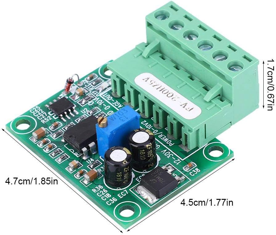
Image 5.1: The FV-200Hz5V module with its physical dimensions (length, width, height) clearly labeled in centimeters and inches.
6. Maintenance
The Walfront FV-200Hz5V module is designed for reliable operation and requires no specific user maintenance. To ensure longevity, keep the module clean and free from dust, moisture, and corrosive substances. Avoid physical impact or excessive force on the components or terminals.
7. Warranty and Support
Specific warranty details for this product are not provided in this manual. For warranty information, technical support, or service inquiries, please refer to the retailer from whom the product was purchased or contact Walfront directly through their official channels.