
1. Product Overview
The Yanmis XL830L is a portable digital multimeter designed for measuring various electrical parameters. It features a clear LCD display with backlight, ensuring readability in diverse lighting conditions. This instrument offers stable performance, high precision, and reliability, making it suitable for laboratories, factories, radio enthusiasts, and household use.
Key features include:
- LCD display with backlight for clear data readings (maximum display value 1999).
- Thickened silicone casing for shock and drop protection, enhancing durability.
- Overload protection function for safe operation.
- Data hold function to freeze readings.
- Low battery indication.
- Capable of measuring AC/DC voltage, DC current, resistance, diode, and transistor (hFE).
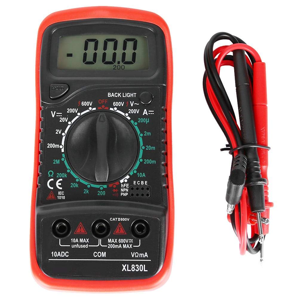
Figure 1: Front view of the Yanmis XL830L Digital Multimeter with test leads connected.
2. Safety Information
Please read and understand all safety instructions before operating the multimeter. Failure to follow these instructions may result in electric shock, fire, or damage to the meter.
- WARNING: To avoid electrical shock, remove test leads before opening the case. Refer to the manual for safety.
- Always ensure the multimeter is set to the correct range and function before making measurements.
- Do not exceed the maximum input values for any range.
- Exercise extreme caution when working with voltages above 30V AC RMS, 42V peak, or 60V DC. These voltages pose a shock hazard.
- Inspect test leads for damaged insulation or exposed metal before use. Replace if damaged.
- Do not operate the meter if it appears damaged or if the case is open.
- Replace the battery as soon as the low battery indicator appears to ensure accurate readings.
- Do not use the meter in wet environments or explosive atmospheres.

Figure 2: Rear view of the multimeter, highlighting the battery compartment and safety warning.
3. Setup and Initial Use
3.1. Battery Installation
The Yanmis XL830L Multimeter requires a 9V, 6F22 battery (not included).
- Ensure the multimeter is turned OFF and disconnect any test leads.
- Locate the battery compartment cover on the back of the unit (refer to Figure 2).
- Unscrew the retaining screw(s) and carefully remove the battery cover.
- Connect a new 9V battery to the battery clips, observing correct polarity.
- Place the battery into the compartment and replace the cover, securing it with the screw(s).
3.2. Connecting Test Leads
The multimeter comes with two test leads (red and black).
- Connect the black test lead to the "COM" (Common) jack.
- For most measurements (voltage, resistance, diode, transistor), connect the red test lead to the "VΩmA" jack.
- For measuring high DC current (up to 10A), connect the red test lead to the "10ADC" jack. Note: This jack is unfused.

Figure 3: Correct connection of test leads to the multimeter's input jacks.
4. Operating Instructions
This section details how to use the various functions of your XL830L Digital Multimeter. Always ensure the test leads are correctly connected and the function dial is set to the appropriate range before making any measurements.
4.1. Measuring DC Voltage (V=)
- Connect the red lead to the "VΩmA" jack and the black lead to the "COM" jack.
- Set the rotary switch to the desired "V=" (DC Voltage) range (e.g., 200mV, 2V, 20V, 200V, 600V). If the voltage is unknown, start with the highest range and work downwards.
- Connect the test probes across the component or circuit to be measured, observing polarity.
- Read the voltage value on the LCD display.
4.2. Measuring AC Voltage (V~)
- Connect the red lead to the "VΩmA" jack and the black lead to the "COM" jack.
- Set the rotary switch to the desired "V~" (AC Voltage) range (e.g., 200V, 600V).
- Connect the test probes across the AC source or component. Polarity is not critical for AC measurements.
- Read the voltage value on the LCD display.

Figure 4: Example of using the multimeter to measure voltage in an electrical panel.
4.3. Measuring DC Current (A=)
- For currents up to 200mA, connect the red lead to the "VΩmA" jack. For currents up to 10A, connect the red lead to the "10ADC" jack. Connect the black lead to the "COM" jack.
- Set the rotary switch to the desired "A=" (DC Current) range (e.g., 200µA, 2mA, 20mA, 200mA, 10A).
- WARNING: To measure current, the multimeter must be connected in series with the circuit. Do not connect it in parallel across a voltage source, as this will cause a short circuit.
- Open the circuit where you want to measure current and insert the multimeter in series.
- Read the current value on the LCD display.
4.4. Measuring Resistance (Ω)
- Connect the red lead to the "VΩmA" jack and the black lead to the "COM" jack.
- Set the rotary switch to the desired "Ω" (Resistance) range (e.g., 200Ω, 2kΩ, 20kΩ, 200kΩ, 2MΩ).
- Ensure the circuit or component to be measured is de-energized before measuring resistance.
- Connect the test probes across the resistor or component.
- Read the resistance value on the LCD display.
4.5. Diode Test
- Connect the red lead to the "VΩmA" jack and the black lead to the "COM" jack.
- Set the rotary switch to the diode symbol (▶|).
- Connect the red probe to the anode and the black probe to the cathode of the diode. A forward voltage drop (typically 0.5V to 0.8V for silicon diodes) will be displayed.
- Reverse the probes. The display should show "OL" (Overload) for a good diode.
4.6. Transistor (hFE) Test
- Set the rotary switch to the "hFE" position.
- Identify if the transistor is NPN or PNP.
- Insert the transistor's emitter, base, and collector leads into the corresponding sockets on the hFE test socket (E, B, C).
- Read the hFE (DC current gain) value on the LCD display.
4.7. Data Hold Function
Press the "HOLD" button to freeze the current reading on the display. Press it again to release the hold and resume live measurements.
4.8. Backlight Function
Press the "BACK LIGHT" button to turn on the display backlight for improved visibility in low-light conditions. Press it again to turn off the backlight.

Figure 5: The multimeter display with the backlight activated for enhanced visibility.
5. Maintenance
5.1. Cleaning
Wipe the meter's casing with a damp cloth and a mild detergent. Do not use abrasives or solvents. Ensure the meter is completely dry before use.
5.2. Battery Replacement
When the low battery indicator appears on the display, replace the 9V battery as described in Section 3.1. Prompt battery replacement ensures accurate measurements and proper device function.
5.3. Storage
If the meter is not to be used for an extended period, remove the battery to prevent leakage and damage. Store the multimeter in a cool, dry place, away from direct sunlight and extreme temperatures.
6. Troubleshooting
- No display or faint display:
- Check battery charge. Replace the 9V battery if low.
- Ensure battery is installed with correct polarity.
- Check for proper contact between battery and terminals.
- "OL" (Overload) displayed:
- The measured value exceeds the selected range. Switch to a higher range.
- For resistance measurement, ensure the circuit is de-energized.
- For diode test, "OL" is normal when probes are reversed on a good diode.
- Inaccurate readings:
- Ensure the correct function and range are selected.
- Check test leads for damage or poor connection.
- Replace the battery if it's low.
- Ensure the component being measured is isolated from the circuit if necessary (e.g., for resistance).
- No reading when measuring current:
- Ensure the multimeter is connected in series with the circuit.
- Verify the red lead is in the correct current jack (VΩmA for mA, 10ADC for 10A).
- Check for open circuit in the test leads or the circuit itself.
7. Specifications
| Function | Range | Accuracy |
|---|---|---|
| DC Voltage (DC V) | 200mV, 2V, 20V, 200V, 600V | ±0.5% |
| AC Voltage (AC V) | 200V, 600V | ±1.0% |
| DC Current (DC A) | 200µA, 2mA, 20mA, 200mA, 10A | ±1.8% |
| Resistance | 200Ω, 2kΩ, 20kΩ, 200kΩ, 2MΩ | ±1.0% |
| Diode Test | Yes | |
| Transistor Test (hFE) | PNP/NPN hFE measurement |
General Specifications:
- Maximum Display: 1999 (3½ digit LCD)
- LCD Size: 45x20mm (1.8x0.8in)
- Input Resistance: 1MΩ
- Power Supply: 9V battery, 6F22 (not included)
- Dimensions: Approximately 135 x 67 x 33 mm (5.3 x 2.6 x 1.3 inches)
- Overload Protection: Yes
- Data Hold: Yes
- Backlight: Yes
- Continuity Measurement: Yes

Figure 6: Physical dimensions of the XL830L Multimeter.
8. Warranty and Support
For information regarding warranty coverage or technical support, please refer to the documentation provided with your purchase or contact the retailer.