
1. Introduction
This manual provides detailed instructions for the AOPUTTRIVER Professional Coating Thickness Gauge, Model UK-HP-1001. This device is designed for non-destructive measurement of coating and paint thickness on various metal substrates. It is widely used in manufacturing, metal processing, chemical industries, and automotive inspection.
The gauge features an automatic 2-in-1 sensor for both ferrous (Fe) and non-ferrous (NF) metals, offering a measurement range of 0-1300um (0-51.2mil). Its portable design and high precision make it an essential tool for professionals and enthusiasts alike.

Image 1.1: The AOPUTTRIVER Coating Thickness Gauge and included accessories.
2. Product Features
The AOPUTTRIVER Coating Thickness Gauge offers a range of features for accurate and convenient measurements:
- Wide Measurement Range: 0 to 1300um (0 to 51.2mil).
- High Precision: Accuracy of ± (3% + 2um) or ± (3% + 0.08mil).
- Fine Resolution: 0.1um for detailed readings.
- Dual Probe Technology: Integrated Fe (ferrous) and NF (non-ferrous) probes for automatic substrate detection.
- Non-Destructive Testing: Measures coating thickness without damaging the surface.
- Multiple Calibration Methods: Supports zero calibration and multi-point calibration (50/100/250/500/1000um).
- User-Friendly Design: Anti-slip grip and compact, pocket-sized form factor (130mm x 62mm x 32mm).
- Large LCD Display: Clear digital readout for easy viewing.
- Unit Switching: Easily switch between micrometers (um) and mils (mil).
- Auto-Backlight: Enhances visibility in various lighting conditions.
- Automatic Power Off: Conserves battery life.

Image 2.1: Overview of the gauge's digital features.
3. Package Contents
Please check the package carefully to ensure all items are present:
- AOPUTTRIVER Coating Thickness Gauge (1 unit)
- 9V Battery (1 unit)
- User Manual (1 unit)
- Iron Substrate (1 unit)
- Aluminum Substrate (1 unit)
- Standard Thickness Calibration Films (50/100/250/500/1000um) (1 set)
- Protective Case (1 unit)
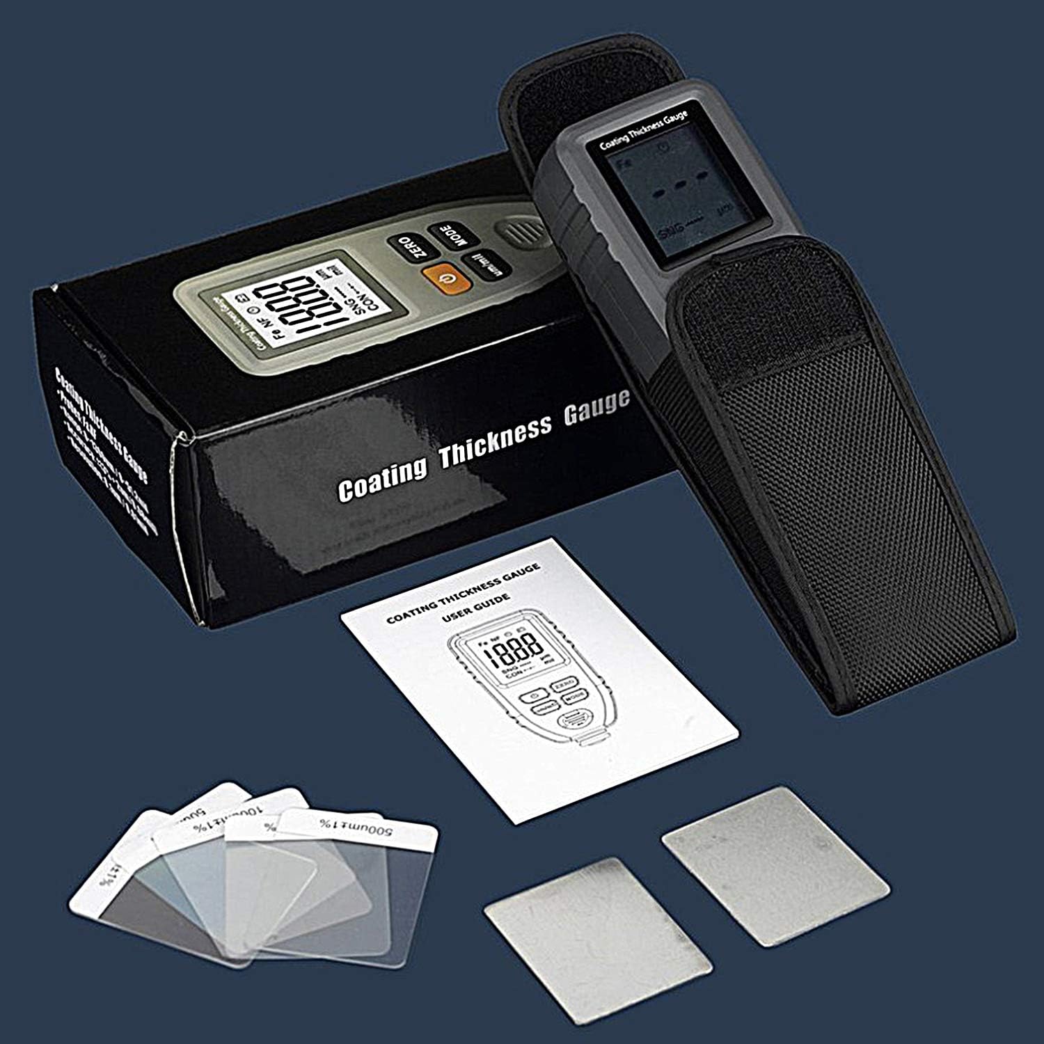
Image 3.1: All items included in the product package.
4. Setup
4.1. Battery Installation
- Locate the battery compartment cover on the back of the device.
- Slide or unclip the cover to open the compartment.
- Insert the included 9V battery, ensuring correct polarity (+/- terminals).
- Close the battery compartment cover securely.
4.2. Initial Power On
Press the POWER button to turn on the device. The LCD display will illuminate, and the device will perform a self-test before entering measurement mode.
5. Operating Instructions
5.1. Power On/Off
- To power on, press the POWER button.
- To power off, press and hold the POWER button for a few seconds until the display turns off, or the device will automatically power off after a period of inactivity.
5.2. Measurement Modes
The gauge supports two measurement modes:
- SNG (Single Measurement Mode): For taking individual readings. Press the probe onto the surface, and the reading will be displayed. Lift the probe and repeat for a new measurement.
- CON (Continuous Measurement Mode): For continuous readings. Keep the probe on the surface and slide it across to get real-time thickness updates.
Press the MODE button to switch between SNG and CON modes.

Image 5.1: Using the gauge in SNG (Single) mode for quick measurements.
5.3. Unit Switching
Press the um/mil button to toggle between micrometers (um) and mils (mil) units.
5.4. Probe Types (Fe & NF)
The gauge automatically detects the substrate material:
- Fe (Ferrous Probe): Used for detecting non-magnetic coatings (e.g., chrome, copper, zinc, varnish, rubber) on magnetic substrates like iron or steel.
- NF (Non-Ferrous Probe): Used for detecting insulating coatings (e.g., paint, anodizing, ceramic) on non-magnetic substrates like aluminum, copper, or brass.

Image 5.2: The dual-function probe for Fe and NF substrates.

Image 5.3: Differentiation between Fe and NF material detection.
5.5. Calibration
Calibration ensures the accuracy of your measurements. It is recommended to calibrate the device before critical measurements or if you suspect inaccurate readings.
- Zero Calibration: Place the probe directly onto the bare iron or aluminum substrate (without any coating). Press the ZERO button. The display should show "0.0" or a value very close to zero.
- Multi-Point Calibration: Use the provided standard thickness calibration films. Place a film (e.g., 100um) on the appropriate substrate (iron for Fe, aluminum for NF). Take a reading. If the reading deviates, adjust the calibration according to the device's specific menu options (refer to the quick start guide for detailed steps if available). Repeat for other calibration films as needed.

Image 5.4: Custom calibration using standard films and substrates.
5.6. Taking a Measurement
- Ensure the device is powered on and calibrated.
- Select the desired measurement mode (SNG or CON).
- Place the probe perpendicularly and firmly onto the coated surface you wish to measure.
- Wait for the reading to stabilize on the LCD display.
- Lift the probe from the surface. For SNG mode, the reading will hold. For CON mode, the reading will update as you move the probe.

Image 5.5: Example of measuring car paint thickness.
6. Maintenance
6.1. Cleaning
- Wipe the device with a soft, dry cloth.
- Do not use abrasive cleaners or solvents, as they may damage the casing or display.
- Keep the probe tip clean and free from debris to ensure accurate readings.
6.2. Storage
- Store the device in its protective case when not in use.
- Keep it in a cool, dry place, away from direct sunlight and extreme temperatures.
- Remove the battery if the device will not be used for an extended period to prevent leakage.
7. Troubleshooting
| Problem | Possible Cause | Solution |
|---|---|---|
| Device does not power on. | Low or dead battery; incorrect battery installation. | Replace the 9V battery; ensure correct polarity. |
| Inaccurate readings. | Device not calibrated; dirty probe tip; unstable placement. | Perform zero and multi-point calibration; clean the probe tip; ensure firm and perpendicular placement. |
| Display is dim or flickering. | Low battery. | Replace the 9V battery. |
| "ERR" or error message on display. | Measurement out of range; sensor malfunction. | Ensure measurement is within 0-1300um range; try recalibrating. If problem persists, contact support. |
8. Specifications
| Parameter | Value |
|---|---|
| Model Number | UK-HP-1001 |
| Measurement Range | 0 - 1300um (0 - 51.2mil) |
| Accuracy | ± (3% + 2um) / ± (3% + 0.08mil) |
| Resolution | 0.1um |
| Dimensions | 130mm x 62mm x 32mm |
| Weight | 110 grams |
| Operating Temperature | 0 °C to 40 °C (32 °F to 104 °F) |
| Operating Humidity | 20% to 90% RH |
| Minimum Measuring Area Diameter | 6 mm |
| Minimum Convex Curvature Radius | 1.5 mm |
| Minimum Concave Curvature Radius | 25 mm |
| Minimum Substrate Thickness | 0.3 mm |
| Power Supply | 1 x 9V Battery (included) |

Image 8.1: Physical dimensions of the product.
9. Warranty and Support
For any questions, technical assistance, or warranty claims, please refer to the contact information provided with your purchase or visit the official AOPUTTRIVER website. Please have your model number (UK-HP-1001) and purchase details ready when contacting support.