Product Overview
The Walfront STC-3018 is a microcomputer intelligent digital display thermostat designed for precise temperature and humidity control. It features a dual screen for simultaneous display of current and set temperatures, making it suitable for various applications requiring automated temperature management, such as in seafood machines and cooling water systems.
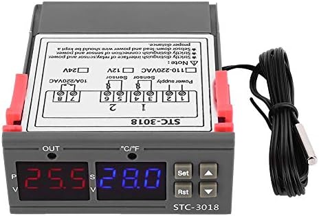
Image: Front view of the Walfront STC-3018 Digital Temperature Controller, showing the dual LED displays and control buttons.
Key Features
- ABS Flame Retardant Plastic Shell: Ensures enhanced safety during operation.
- Microcomputer Intelligent Digital Display: Dual screen for displaying both current and set temperatures.
- Included NTC Sensor: Comes with a 1-meter long sensor for convenient temperature detection.
- High Accuracy: Provides precise temperature measurement and control.
- Versatile Application: Ideal for automatic switching of refrigeration and heating devices, including seafood machines and cooling water systems.
Specifications
| Parameter | Value |
|---|---|
| Product Model | STC-3018 |
| Optional Voltage | 12V/24V/110V - 220VAC |
| Temperature Control Range | -55°C to 120°C |
| Screen Display | Dual Screen Dual Display |
| Machine Power Consumption | Less Than 3W |
| Temperature Measurement Accuracy | ±1 °C (-50 °C ~ 70 °C) |
| Resolution | 0.1 °C |
| Sensor Type | NTC Sensor (line length approx. 1 meter) |
| Ambient Temperature | 0°C to 60°C |
| Relative Humidity | 20%~85% (no condensation) |
| Machine Size | Approx. 75 x 34.5 x 85mm / 3 x 1.4 x 3.3in |
| Installation Opening | Approx. 71 x 29mm / 2.8 x 1.1in |
| Housing Material | ABS flame retardant plastic shell |
| Item Weight | 3.87 ounces |
| UPC | 713135318215 |

Image: The STC-3018 controller showing its physical dimensions of 71mm (2.8in) and 29mm (1.1in) for installation opening.
Installation and Setup
Panel Introduction
Familiarize yourself with the control panel components before installation.
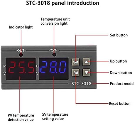
Image: Diagram illustrating the STC-3018 control panel, labeling the indicator light, temperature unit conversion light, Set button, Up button, Down button, Reset button, PV temperature detection value, and SV temperature setting value.
Wiring Diagram
Proper wiring is crucial for the safe and correct operation of the device. Refer to the diagrams below for connection instructions.

Image: Two wiring diagrams for the STC-3018. The top diagram shows wiring for a load with an independent power supply, while the bottom diagram shows wiring for a load with the same power supply as the controller. Both diagrams indicate connections for power supply, sensor, and output.
Important Note: Strictly distinguish the interface of the relay/sensor and power supply. The sensor down-lead and power wire should be kept a proper distance apart to avoid interference.
Operating Instructions
Setting Temperature Parameters
- Power On: Ensure the device is correctly wired and powered on. The dual LED displays will show the current temperature (PV) and the set temperature (SV).
- Access Settings: Press the Set button once to enter the temperature setting mode. The SV display will flash.
- Adjust Temperature: Use the Up (▲) and Down (▼) buttons to adjust the desired set temperature (SV).
- Confirm Setting: Press the Set button again to confirm the new setting and exit the setting mode. The device will now operate according to the new set temperature.
- Reset: To reset the device, press the Rst button.
Temperature Unit Conversion
The STC-3018 supports temperature unit conversion. Refer to the panel introduction image for the location of the temperature unit conversion light. Specific instructions for changing units (e.g., Celsius to Fahrenheit) are typically found in the full product manual or by holding the 'Set' button for an extended period to access advanced parameters. Please consult the manufacturer's website or contact support for detailed steps if needed.
Maintenance
- Cleaning: Regularly wipe the device with a soft, dry cloth. Do not use abrasive cleaners or solvents.
- Sensor Care: Ensure the temperature sensor is clean and free from debris. Avoid bending or damaging the sensor cable.
- Environmental Conditions: Operate the controller within the specified ambient temperature and humidity ranges (0~60°C, 20%~85% relative humidity, no condensation) to ensure longevity.
- Connection Check: Periodically inspect all wiring connections to ensure they are secure and free from corrosion.
Troubleshooting
| Problem | Possible Cause | Solution |
|---|---|---|
| Device does not power on. | No power supply or incorrect wiring. | Check power connections and ensure correct voltage (12V/24V/110V-220VAC) is supplied. Verify wiring against the diagram. |
| Temperature reading is inaccurate. | Damaged or improperly connected sensor. Sensor not in optimal measuring position. | Inspect sensor for physical damage. Ensure sensor is securely connected. Reposition sensor to accurately measure the desired area. |
| Controller not switching heating/cooling. | Incorrect temperature settings. Output wiring issue. | Verify the set temperature (SV) and ensure it aligns with the desired operation (heating or cooling). Check the output wiring to the connected device. |
| Display shows error code. | Sensor fault or internal error. | Refer to the full product manual for specific error codes. Often indicates a sensor open circuit or short circuit. Replace sensor if faulty. |
If the problem persists after attempting these solutions, please contact Walfront customer support.
Warranty and Support
For warranty information and technical support, please refer to the documentation included with your purchase or visit the official Walfront website. Keep your purchase receipt for warranty claims.
Walfront Store: https://www.amazon.com/stores/Walfront/page/FECAC109-E5D3-4C74-B6F1-3FA643B2EA7D


