1. Introduction
This manual provides detailed instructions for the installation, operation, and maintenance of the Jectse MPT-7210A MPPT Solar Charge Controller. This device is designed to efficiently manage power from solar panels to charge various battery types, including lithium and lead-acid batteries, in DC12-60V systems.
Key features include:
- MPPT (Maximum Power Point Tracking) and DC-DC working modes.
- Adjustable output voltage (DC15-90V) and current (0-10A).
- Maximum output power of 600W, suitable for 100W-600W solar panels.
- Integrated LCD display for real-time monitoring.
- Built-in protection against reverse connection and overload.
- Efficient heat dissipation with an aluminum alloy casing and fan.
2. Safety Information
Please read and understand all safety instructions before installing or operating the controller. Failure to follow these instructions may result in electric shock, fire, or severe injury.
- Ensure all connections are secure and correctly polarized to prevent damage to the controller and connected devices.
- Always disconnect power from the solar panel and battery before making or breaking connections.
- Do not attempt to disassemble or repair the controller. Contact qualified personnel for service.
- Install the controller in a well-ventilated area, away from flammable materials and moisture.
- The controller features MOS reverse connection protection at both input and output terminals, and an automatic circuit cut-off in case of overload. However, proper installation is crucial for safe operation.
3. Product Overview
The Jectse MPT-7210A controller features a compact design with an intuitive LCD display and control buttons. The robust aluminum alloy casing ensures durability and efficient heat management.
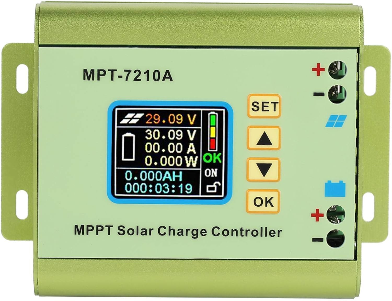
Figure 3.1: Front view of the Jectse MPT-7210A MPPT Solar Charge Controller, showing the LCD screen and control buttons.
3.1 Components
- LCD Display: 160*128 TFT color screen showing input/output voltage, current, power, charging time, and battery status.
- Control Buttons: "SET", "Up Arrow", "Down Arrow", and "OK" for navigation and parameter adjustment.
- Solar Input Terminals: Marked with a solar panel icon and '+' / '-' for connecting the solar panel.
- Battery Output Terminals: Marked with a battery icon and '+' / '-' for connecting the battery.
- Cooling Fan: Located on the side for active heat dissipation.
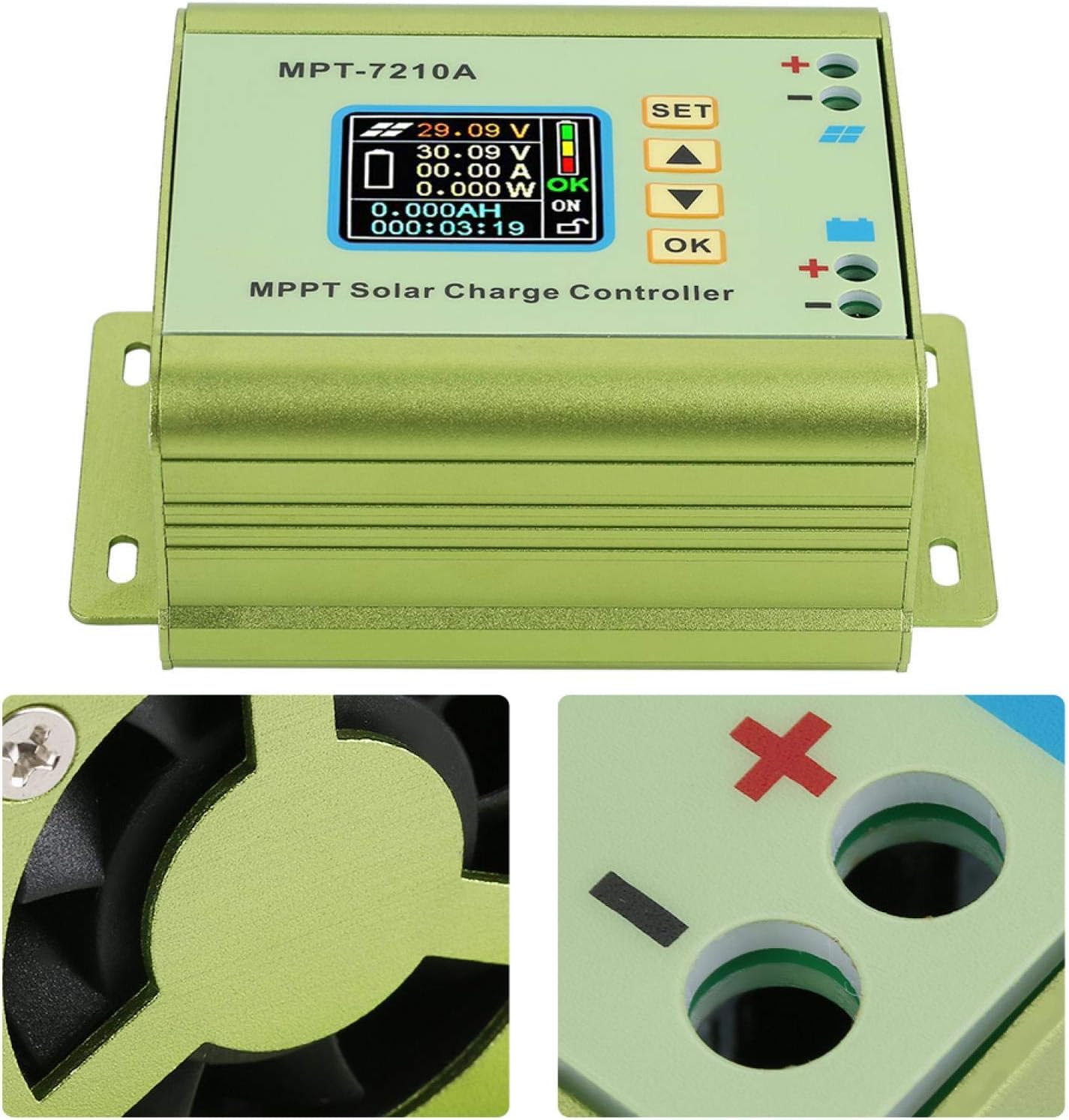
Figure 3.2: Detail of the cooling fan and battery connection terminals.

Figure 3.3: Close-up of the LCD display and the side-mounted cooling fan.
4. Setup and Installation
Follow these steps for proper installation of the MPT-7210A controller. Ensure all power sources are disconnected before proceeding.
4.1 Connection Diagram

Figure 4.1: Connection diagram showing solar panel input and battery output connections.
4.2 Wiring Steps
- Connect the Battery: Connect the positive (+) and negative (-) terminals of your battery to the corresponding battery output terminals on the controller. Ensure correct polarity.
- Connect the Solar Panel: Connect the positive (+) and negative (-) terminals of your solar panel to the corresponding solar input terminals on the controller. Ensure correct polarity.
- Verify Connections: Double-check all wiring for correct polarity and secure connections.
- Power On: Once all connections are verified, the controller will power on and display information on the LCD screen.
Note: Always connect the battery first, then the solar panel. Disconnect in reverse order (solar panel first, then battery).
5. Operating Instructions
The MPT-7210A controller offers two primary working modes and allows for adjustable output parameters.
5.1 LCD Display Overview
The 160*128 TFT color LCD display provides real-time data:
- Input Voltage (from solar panel)
- Output Voltage (to battery)
- Output Current
- Output Power
- Charging Time
- Battery Charge Status
5.2 Working Modes
The controller supports two selectable working modes:
- MPPT Mode: (Maximum Power Point Tracking) - Ideal for photovoltaic panel applications. This mode optimizes the power output from the solar panel to maximize charging efficiency.
- DC-DC Mode: Used for boost power supply applications, where the output voltage needs to be higher than the input voltage.
To switch between modes or adjust parameters, use the "SET", "Up Arrow", "Down Arrow", and "OK" buttons on the front panel. Refer to the on-screen menu for specific navigation and setting procedures.
5.3 Parameter Adjustment
The controller allows adjustment of output voltage and current:
- Output Voltage: Adjustable from DC15-90V, suitable for 24V, 36V, 48V, 60V, and 72V battery systems.
- Output Current: Adjustable from 0-10A.
The controller also has 20 groups of data storage for user-defined settings.
6. Maintenance
The Jectse MPT-7210A controller is designed for low maintenance. Regular checks can ensure optimal performance and longevity.
- Cleaning: Periodically clean the exterior of the controller with a dry, soft cloth. Ensure the cooling fan vents are free from dust and debris to maintain proper airflow.
- Connection Check: Annually inspect all wiring connections to ensure they are tight and free from corrosion.
- Environmental Conditions: Ensure the controller remains in a suitable environment as specified in the product specifications (e.g., temperature, humidity).
7. Troubleshooting
If you encounter issues with your MPT-7210A controller, refer to the following common problems and solutions:
| Problem | Possible Cause | Solution |
|---|---|---|
| No display/No power | Incorrect battery connection, low battery voltage, faulty wiring. | Check battery polarity and connections. Ensure battery voltage is within the controller's operating range. |
| No charging from solar panel | Solar panel not connected, insufficient sunlight, faulty solar panel, incorrect solar panel polarity. | Verify solar panel connections and polarity. Ensure adequate sunlight. Test solar panel output. |
| Overload protection activated | Output current exceeds maximum limit. | Reduce the load connected to the battery or adjust output current settings if applicable. The controller will automatically cut off the circuit in case of overload. |
| Incorrect voltage/current readings | Loose connections, sensor issue. | Check all wiring connections. If the problem persists, contact support. |
8. Specifications
Detailed technical specifications for the Jectse MPT-7210A MPPT Solar Charge Controller.

Figure 8.1: Physical dimensions of the controller.
| Feature | Detail |
|---|---|
| Model | MPT-7210A |
| Material | Aluminum Alloy |
| Color | Green |
| Display | 160*128 TFT Color LCD |
| Input Voltage | DC12-60V |
| Output Current | 0-10A (Adjustable) |
| Output Power | 20-600W |
| Working Mode | MPPT, DC-DC (Selectable) |
| Output Voltage | DC15-90V (Adjustable for 24V/36V/48V/60V/72V systems) |
| Dimensions (L*W*H) | 131*96*55mm (5.16"L x 3.78"W x 2.17"H) |
| Weight | Approx. 440g (15.5oz) |
| UPC | 713135624750 |
| Item Model Number | Jectseg3dost91pn |
9. Product Video
Watch this video for a visual overview of the Jectse MPT-7210A MPPT Solar Charge Controller.
Video 9.1: Overview of the Jectse MPT-7210A MPPT Solar Charge Controller, demonstrating its features and design.
10. Warranty and Support
For warranty information and technical support regarding your Jectse MPT-7210A MPPT Solar Charge Controller, please refer to the documentation provided at the time of purchase or contact Jectse customer service directly. Contact details can typically be found on the manufacturer's official website or through your retailer.


