1. Introduction
This manual provides detailed instructions for the installation, operation, and maintenance of your Suuwer S701 Non-Programmable Thermostat. This thermostat is designed for use with 1 Heat/1 Cool conventional single-stage heating and cooling systems. Please read this manual thoroughly before installation and operation to ensure proper function and safety.

Image 1.1: Front view of the Suuwer S701 Non-Programmable Thermostat, displaying room temperature and set temperature on a blue backlit screen.
2. Safety Information
- Always turn off power to the heating/cooling system at the main fuse or circuit breaker panel before installing or servicing the thermostat.
- This thermostat operates on 24VAC power or 2 AAA batteries. Do not connect to line voltage (120-240V) systems.
- If you are inexperienced with electrical wiring, it is recommended to seek professional assistance for installation.
- Ensure all wiring connections are secure to prevent short circuits or damage to the system.
3. Package Contents
Verify that all items are present in your package:
- Suuwer S701 Thermostat Unit
- Installation Manual
- Cable Labels
- Mounting Screws (2)
- Wall Anchors (2)

Image 3.1: Illustration of the Suuwer S701 thermostat and its included accessories.
4. System Compatibility
The Suuwer S701 thermostat is designed for specific HVAC systems. Please review the compatibility information carefully before installation.
4.1 Compatible Systems
- Conventional Single-Stage Heating & Cooling (with C-wire or without C-wire)
- Gas Fireplace (24 Volts)
- Gas / Oil / Electric Furnace (Heating only)
- Boiler Radiant Heating Only
- Furnace Forced-Air Heating Only
- Cooling Only (with C-wire or without C-wire)
Note: Verify your existing thermostat base is wired with 2 to 5 wires. Systems with 6 to 8 wires are generally not supported by this model.
4.2 Incompatible Systems
- Multistage Heating & Cooling (e.g., 1H/2C, 2H/2C)
- HVAC Heat Pump Systems (e.g., 2H/1C, 4H/2C)
- PTACs (Packaged Terminal Air Conditioners)
- 3-wire Hydronic (Hot Water) Systems
- Dual Fuel/Hybrid Heating Systems
- Line Voltage Systems (120-240V electric baseboards heat)
- Mini Split Heat Pump Air Conditioners
- RV Air Conditioners (Mach and Roughneck series)
- Convectors
- Radiant Ceiling Heat
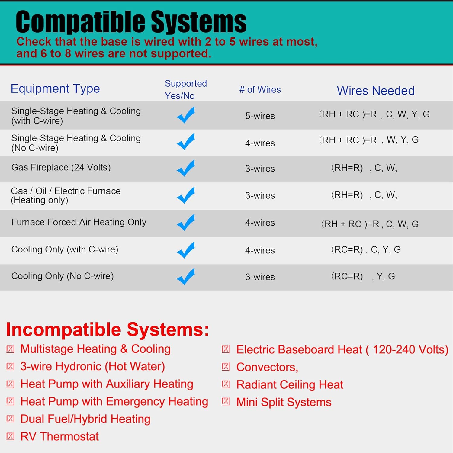
Image 4.1: Detailed compatibility chart for the Suuwer S701 thermostat.
5. Setup and Installation
Follow these steps for proper installation. It is recommended to take a picture of your old thermostat's wiring before disconnecting any wires.
5.1 Removing Your Old Thermostat
- Turn off power: Locate the circuit breaker or fuse box that controls your heating and cooling system and turn off the power.
- Remove cover: Carefully remove the cover of your old thermostat.
- Photograph wiring: Take a clear picture of the wiring connections, noting which wire is connected to each terminal.
- Label wires: Use the provided cable labels to mark each wire according to its terminal designation (e.g., R, W, Y, G, C).
- Disconnect wires: Disconnect the wires from the old thermostat terminals.
- Remove old base: Unscrew and remove the old thermostat's mounting base from the wall.
5.2 Mounting the New Thermostat
- Position base: Hold the new Suuwer S701 thermostat base against the wall where you want to mount it.
- Mark screw holes: Mark the positions for the mounting screws. If possible, use existing screw holes.
- Drill holes: If new holes are needed, drill pilot holes and insert the wall anchors.
- Secure base: Pull the wires through the opening in the thermostat base and secure the base to the wall using the provided screws.
5.3 Wiring Connections
Connect the labeled wires to the corresponding terminals on the Suuwer S701 thermostat base. Refer to the wiring diagram below and your photograph for accuracy.
- R/RC: 24VAC power (often jumpered, see diagram)
- G: Indoor blower (fan)
- Y: 1st-stage cool
- W: 1st-stage heat
- C: Common wire (optional for battery-powered operation, but recommended for continuous backlight)

Image 5.1: Wiring diagram and system switch setting for the Suuwer S701 thermostat.
5.4 Setting the System Switch (GAS/ELEC)
On the back of the thermostat unit, locate the small switch labeled 'GAS' and 'ELEC'.
- If you have a gas or oil furnace, set the switch to GAS.
- If you have an electric furnace, set the switch to ELEC.
5.5 Installing Batteries
The thermostat can be powered by 24VAC or 2 AAA batteries. Batteries are required for operation if no C-wire is connected. Even with a C-wire, batteries provide backup power.
- Open the battery compartment on the front of the thermostat.
- Insert two new AAA alkaline batteries, ensuring correct polarity (+/-).
- Close the battery compartment.
5.6 Attaching the Thermostat to the Base
Align the thermostat unit with the mounted base and gently push it into place until it clicks securely.
5.7 Restoring Power
Once the thermostat is securely mounted and wired, turn the power back on at the main circuit breaker or fuse box.
6. Operating Instructions
The Suuwer S701 is a non-programmable thermostat, offering straightforward manual control of your home's temperature.

Image 6.1: Display and controls of the Suuwer S701 thermostat.
6.1 Display Overview
The large LCD with blue backlight shows the current room temperature and the set temperature. The backlight activates for 10 seconds when any button is pressed.
- Room: Displays the current ambient temperature.
- Set At: Displays the desired temperature setting.
- Cool/Heat/Off: Indicates the current system mode.
- Fan ON/AUTO: Indicates the current fan mode.
6.2 Adjusting Temperature
Use the + (Up) and - (Down) buttons on the right side of the thermostat to adjust the desired temperature setting. Each press changes the temperature by 1 degree Fahrenheit.
6.3 System Mode Selection
Use the SYSTEM switch located at the bottom right of the thermostat to select the operating mode:
- COOL: Activates the cooling system when the room temperature rises above the set temperature.
- HEAT: Activates the heating system when the room temperature falls below the set temperature.
- OFF: Turns off both heating and cooling systems.
6.4 Fan Mode Selection
Use the FAN switch located at the bottom left of the thermostat to select the fan operating mode:
- AUTO: The fan runs only when the heating or cooling system is actively operating. This is the most common and energy-efficient setting.
- ON: The fan runs continuously, regardless of whether the heating or cooling system is active.
6.5 Adjusting Temperature Swing (Cycle Rate)
The temperature swing, also known as cycle rate or differential, determines how much the temperature can vary from your setpoint before the system turns on. A smaller swing results in more frequent, shorter cycles, while a larger swing results in less frequent, longer cycles.
The swing is adjustable from 0.2°F to 2°F. The factory default is 0.5°F for both heating and cooling.

Image 6.2: Thermostat display showing the temperature swing setting.
To adjust the temperature swing:
- Press and hold the FAN button for approximately 3 seconds until the display changes to show the current swing setting.
- Use the + (Up) or - (Down) buttons to adjust the swing value.
- Press the FAN button again to toggle between heating and cooling swing settings.
- The thermostat will automatically save the setting after a few seconds of inactivity.
7. Maintenance
7.1 Battery Replacement
When the low battery indicator (a battery icon) appears on the display, it is time to replace the batteries. Replace with two new AAA alkaline batteries. Refer to Section 5.5 for battery installation steps.
7.2 Cleaning
Wipe the thermostat's exterior with a soft, damp cloth. Do not use abrasive cleaners or solvents.
8. Troubleshooting
If you encounter issues with your thermostat, refer to the following common problems and solutions:
| Problem | Possible Cause | Solution |
|---|---|---|
| Display is blank | No power, dead batteries, or tripped circuit breaker. | Check batteries and replace if necessary. Ensure power is on at the circuit breaker. Verify wiring connections. |
| Heating/Cooling system not responding | Incorrect system mode, incorrect wiring, or system issue. | Ensure SYSTEM switch is set to HEAT or COOL. Verify wiring. Check if furnace/AC unit has power. |
| Temperature reading seems inaccurate | Thermostat location, or calibration needed. | Ensure thermostat is not in direct sunlight or near heat sources. The thermostat has a room temperature calibration adjustment for +/-1-degree F. Consult the full installation manual for advanced settings. |
| Low Battery Indicator (battery icon) | Batteries are low. | Replace with two new AAA alkaline batteries immediately. |
| Compressor short cycling (turning on/off too frequently) | Temperature swing set too low. | Adjust the temperature swing to a higher value (e.g., 1.0°F or 1.5°F). |
For more detailed troubleshooting, please refer to the Troubleshooting Guide (PDF).
9. Specifications
- Model: S701
- Product Dimensions: 0.98"D x 4.72"W x 3.86"H
- Item Weight: 6.7 ounces (0.42 Pounds)
- Color: Blue Backlight
- Material: Plastic
- Display Type: LCD with Blue Backlight
- Screen Size: 4.5 Inches
- Control Type: Push Button / Button Control
- Mounting Type: Wall Mount
- Power Source: 24 Volts (AC) or 2 AAA Batteries
- Temperature Control Range: 44°F to 90°F
- Room Temperature Display Range: 41°F to 95°F
- Temperature Accuracy: +/-1°F
- Special Features: Non-Programmable, Separate Heating and Cooling Swing (0.2°F to 2°F), Low Battery Indicator, 5 Minute Compressor Delay Protection (Selectable ON or OFF)
- UPC: 709327753278
10. Warranty and Support
10.1 Warranty Information
The Suuwer S701 Non-Programmable Thermostat comes with a 2-year worry-free warranty from the date of purchase. This warranty covers defects in materials and workmanship under normal use. Please retain your proof of purchase for warranty claims.
10.2 Customer Support
For technical assistance, troubleshooting, or warranty inquiries, please contact Suuwer customer service. We offer 24-hour customer service to assist you.
Additional Resources:


