
BSIDE FWT82
BSIDE FWT82 Dual Mode Network Cable Tracker User Manual
Model: FWT82
Introduction
The BSIDE FWT82 is a versatile dual-mode network cable tracker designed for efficient and accurate testing of RJ45 and RJ11 network cables. It features both digital and analog modes, offering enhanced anti-interference capabilities and adjustable collation speed for various testing environments. This manual provides detailed instructions for the safe and effective use of your device.
Safety Information
To ensure safe operation and avoid damage to the device or injury, please read and follow all safety instructions.
- The wire tracker probe features an insulated ABS design to enhance safety and protect against electric shock.
- This device conforms to CE, FCC, RoHS, and IEC61010-1 600V CAT III, pollution class II safety standards.
- Do not use the device if it appears damaged or if the battery compartment is not securely closed.
- Ensure correct battery polarity when installing batteries.
- Operating temperature range: 0-40°C (32-104°F), maximum 80% relative humidity (non-condensing).
- Storage temperature range: -10-50°C (14-122°F), maximum 80% relative humidity (non-condensing).
- Altitude: Less than 2000m.
- Anti-explosion rating: IP40.
Package Contents
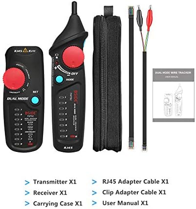
Image Description: This image displays the complete package contents of the BSIDE FWT82. It includes the main transmitter unit, the receiver unit, a carrying case, an RJ45 adapter cable, a clip adapter cable (with alligator clips), and a user manual. These components are essential for various cable testing functions.
Verify that all items are present in the package:
- Transmitter (x1)
- Receiver (x1)
- Carrying Case (x1)
- RJ45 Adapter Cable (x1)
- Clip Adapter Cable (x1)
- User Manual (x1)
Setup
Battery Installation
Both the transmitter and receiver units require a 6F22/9V battery (not included). To install:
- Locate the battery compartment cover on the back of both the transmitter and receiver.
- Open the cover.
- Insert a 6F22/9V battery, ensuring correct polarity (+/-).
- Close the battery compartment cover securely.
Operating Instructions
1. Dual Mode Wire Tracking (Digital & Analog)

Image Description: This image illustrates the dual-mode wire tracking capability of the BSIDE FWT82. It shows both the transmitter and receiver units in operation, with visual cues indicating signal detection. The digital mode offers more accurate tracking, while the analog mode provides a longer tracking range (up to 1000m). The device is designed for anti-interference and anti-noise performance.
The FWT82 offers both digital and analog modes for wire tracking. Digital mode provides higher accuracy, while analog mode allows for a longer tracking distance (up to 1000m).
- Connect the network cable to be traced to the RJ45 or RJ11 port on the transmitter. For non-RJ45/RJ11 cables, use the clip adapter cable.
- Turn on the transmitter and select the desired mode (Digital or Analog) using the mode switch.
- Turn on the receiver.
- Use the receiver's probe to scan along the cable path. The receiver will emit an audible tone and/or visual indicators (LEDs) when it detects the signal from the transmitter.
- The anti-interference and anti-noise design helps in quickly locating the target cable.
2. Network Cable Collation (Wire Mapping)

Image Description: This image demonstrates the network cable collation function, also known as wire mapping, of the BSIDE FWT82. Both the transmitter and receiver units are connected to a network cable, and the LEDs on both devices illuminate sequentially to indicate the wiring order and detect any breaks or miswires. The display shows a timer, suggesting the test can be completed quickly, within 3 seconds.
This function allows you to check the wiring sequence of network cables (RJ45) and identify open circuits, short circuits, cross-overs, or split pairs.
- Connect one end of the RJ45 cable to the transmitter's RJ45 port and the other end to the receiver's RJ45 port.
- Turn on both units.
- Initiate the collation test. The LEDs on both units will light up in sequence, indicating the wiring status.
- Observe the LED patterns to identify any wiring faults. A normal cable will show corresponding LEDs lighting up in order on both units.
- The speed of the network cable collation is adjustable, allowing for faster testing.
3. Continuity Checking (Wire Troubleshoot)

Image Description: This image demonstrates the continuity checking function of the BSIDE FWT82. The transmitter unit is connected to a yellow cable using the clip adapter cable (alligator clips). This setup allows for testing the continuity of various types of wires, not just network cables, to identify breaks or open circuits.
Use this function to check for continuity in various wires, including non-network cables, using the clip adapter cable.
- Connect the clip adapter cable to the transmitter.
- Attach the alligator clips to the ends of the wire you wish to test for continuity.
- Select the continuity mode on the transmitter.
- The device will indicate if there is a continuous path (closed circuit) or a break (open circuit) in the wire.
4. Sensitivity Adjustment

Image Description: This image highlights the adjustable sensitivity feature of the BSIDE FWT82 receiver. It shows a hand adjusting the red rotary knob on the receiver, which controls the sensitivity. This allows users to fine-tune the detection range and precision, making it easier to pinpoint cables in complex environments or reduce interference from nearby wires.
The receiver features an adjustable sensitivity knob to fine-tune the detection range and precision.
- Rotate the sensitivity knob on the receiver to increase or decrease its detection range.
- Adjust sensitivity to avoid interference from adjacent cables or to locate a specific cable more precisely.
5. Switching Test Modes

Image Description: This image illustrates the one-button switching test mode feature of the BSIDE FWT82. It shows the receiver unit with its red rotary knob and blue button. The blue button is used to conveniently switch between different test modes, streamlining the operation and making it more efficient for various testing tasks.
The FWT82 is designed with a dual knob system for efficient function switching, allowing independent operation of the transmitter or receiver.
- Use the dedicated mode switch/button on each unit to toggle between different testing functions (e.g., Digital, Analog, Continuity, Collation).
- This design allows for quick and convenient mode selection during operation.
Maintenance
- Cleaning: Wipe the device with a soft, dry cloth. Do not use abrasive cleaners or solvents.
- Storage: When not in use for extended periods, remove the batteries to prevent leakage. Store the device in its carrying case in a cool, dry place, away from direct sunlight and extreme temperatures.
- Battery Replacement: Replace batteries when the low battery indicator appears or when the device's performance degrades.
Troubleshooting
| Problem | Possible Cause | Solution |
|---|---|---|
| Device does not power on. | Dead or incorrectly installed batteries. | Replace batteries with new 6F22/9V batteries, ensuring correct polarity. |
| No signal detected during wire tracking. |
|
|
| Inaccurate wire mapping results. | Poor connection or damaged cable. | Ensure RJ45 connectors are fully inserted. Inspect cable for physical damage. |
| Excessive noise/interference during tracking. | High electromagnetic interference in the environment. | Switch to digital mode for better anti-interference performance. Reduce receiver sensitivity if necessary. |
Specifications
| Feature | Detail |
|---|---|
| Model | FWT82 |
| Operating Temperature & Humidity | 0-40°C (32-104°F), max 80% RH (non-condensing) |
| Storage Temperature & Humidity | -10-50°C (14-122°F), max 80% RH (non-condensing) |
| Altitude | Less than 2000m |
| Anti-explosion Rating | IP40 |
| Distance of Emitting Signal | >1000m |
| Safety Class | IEC61010-1 600V CAT III, pollution class II |
| Emitter Battery | 6F22/9V (not included) |
| Receiver Battery | 6F22/9V (not included) |
| Product Weight | 0.180 kg |
| Package Weight | 0.270 kg |
| Product Size (Receiver) | 17.5 x 4.5 x 3.5 cm |
| Product Size (Transmitter) | 12 x 4.8 x 3.4 cm |
| UPC | 744702701093 |
Related documentsFWT82


Ask a question about this manual
Ask about setup, troubleshooting, compatibility, parts, safety, or missing instructions. Manuals+ will review the question and use this page’s manual context to help answer it.