
Yoidesu Yoidesud3i5g9y6rg
Yoidesu RJ11 RJ45 Cable Tester Line Finder Instruction Manual
Model: Yoidesud3i5g9y6rg

Image: The Yoidesu RJ11 RJ45 Cable Tester Line Finder, including both the emitter and receiver units, neatly stored within its protective black carrying case.
Introduction
This manual provides comprehensive instructions for the safe and effective use of your Yoidesu Handheld RJ11 RJ45 Cable Tester Line Finder. This device is designed for professionals and enthusiasts to efficiently test network and telephone cables, identify wiring faults, and trace lines. Please read this manual thoroughly before operation and retain it for future reference.
Safety Information
- Do not connect the device to live circuits with voltage exceeding 60V DC or 48V AC.
- Ensure batteries are inserted with correct polarity.
- Remove batteries if the device will not be used for an extended period.
- Keep the device dry and clean. Avoid exposure to extreme temperatures or humidity.
- Do not attempt to disassemble or modify the device. Refer all servicing to qualified personnel.
Package Contents
Verify that all items listed below are present in your package:
- 1 x Cable Emitter
- 1 x Cable Receiver
- 1 x RJ11 Cable
- 1 x RJ45 Cable
- 1 x Earphone
- 1 x Cable with Clamp (Alligator Clips)
- 1 x Black Bag

Image: All components included in the Yoidesu Cable Tester package, neatly arranged. This includes the yellow emitter and receiver units, an RJ11 cable, an RJ45 cable, an earphone, a cable with alligator clips, and a black carrying bag.
Product Overview
The Yoidesu Cable Tester consists of two main units: the Emitter (or Toner) and the Receiver (or Probe).

Image: The yellow Yoidesu Cable Tester Emitter and Receiver units displayed side-by-side. The emitter has RJ11 and RJ45 ports, while the receiver has a metal probe tip.
Emitter Unit (Toner)
- RJ11 Port: For connecting telephone lines.
- RJ45 Port: For connecting Ethernet network cables.
- SCAN/OFF/TEST Switch: Selects operating mode.
- STATUS LEDs: Indicate cable status during testing.
- VERIFY Button: Used for specific testing functions.
- G Port: Ground connection.

Image: A detailed view of the Yoidesu Cable Tester Emitter, highlighting the RJ11 and RJ45 ports for connecting different types of cables.
Receiver Unit (Probe)
- Probe Tip: Used to detect the signal from the emitter.
- POWER Button: Turns the receiver on/off.
- PUSH TO TEST Button: Activates the probe for signal detection.
- Volume Control: Adjusts the audio output for tracing.
- Earphone Jack: For connecting the included earphone.
Setup
Battery Installation
- Locate the battery compartments on the back of both the Emitter and Receiver units.
- Slide open the battery covers.
- Insert one 9V battery into each unit, ensuring correct polarity (+/-).
- Close the battery covers securely.

Image: The Yoidesu Cable Tester Emitter and Receiver units with their battery compartments open, illustrating the correct placement for two 9V batteries.
Operating Instructions
1. Line Tracing (Wire Tracking)
This function helps to quickly locate a specific wire within a bundle of cables.
- Connect the cable to be traced to the appropriate port (RJ11 or RJ45) on the Emitter unit. For non-standard cables, use the provided cable with alligator clips.
- Set the Emitter's switch to the "SCAN" position.
- Turn on the Receiver unit by pressing the POWER button.
- Use the Receiver's probe tip to scan the bundle of wires. The Receiver will emit an audible tone when it detects the signal from the traced wire.
- Adjust the volume on the Receiver for comfortable listening. For noisy environments, connect the earphone.
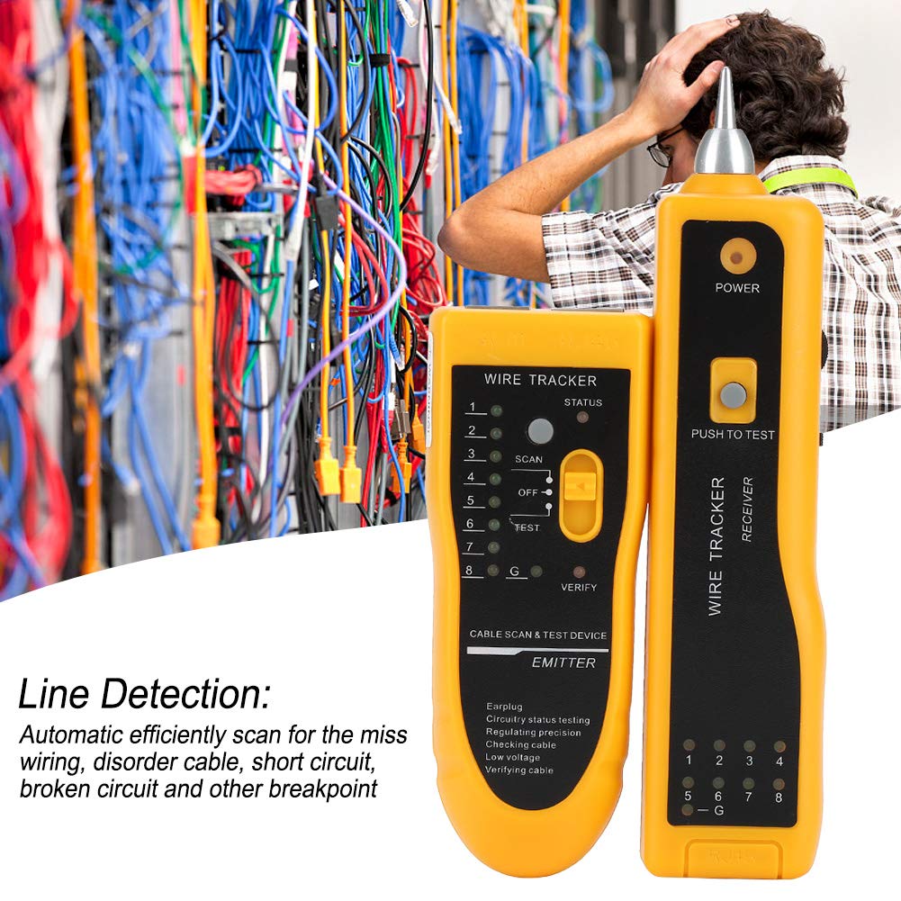
Image: A technician using the Yoidesu Cable Tester Receiver to identify a specific cable within a complex wiring setup, demonstrating the line tracing capability.
2. Line Detection (Cable Scan & Test)
This function automatically scans for wiring faults such as miss-wiring, disorder, short circuits, and broken circuits in network and telephone cables.
- Connect one end of the cable to be tested to the appropriate port (RJ11 or RJ45) on the Emitter unit.
- Connect the other end of the cable to the corresponding port on the Receiver unit.
- Set the Emitter's switch to the "TEST" position.
- Observe the STATUS LEDs on both the Emitter and Receiver. The LEDs will light up sequentially, indicating the continuity of each wire.
- Interpretation of LED patterns:
- Sequential lighting (1-8): Indicates correct wiring.
- Non-sequential lighting: Indicates miss-wiring or disorder.
- No light for a specific number: Indicates an open circuit or broken wire.
- Multiple lights simultaneously: Indicates a short circuit.
3. Continuity Checking
Use the alligator clip cable to check continuity of non-standard wires or components.
- Connect the alligator clip cable to the Emitter unit.
- Clip the alligator clips to the two points of the wire or component you wish to test for continuity.
- Set the Emitter's switch to "TEST".
- If continuity exists, the corresponding LED on the Emitter will light up.
Maintenance
- Cleaning: Wipe the device with a soft, dry cloth. Do not use abrasive cleaners or solvents.
- Battery Replacement: Replace batteries when the power indicator lights dim or the device stops functioning correctly. Refer to the "Battery Installation" section for instructions.
- Storage: Store the device in its protective case in a cool, dry place when not in use. Remove batteries for long-term storage.
Troubleshooting
| Problem | Possible Cause | Solution |
|---|---|---|
| No power/Device not turning on | Dead or incorrectly installed batteries. | Replace batteries, ensuring correct polarity. |
| No tone during line tracing | Emitter not in SCAN mode; Receiver off; Cable not connected; Signal too weak. | Ensure Emitter is in SCAN mode. Turn on Receiver. Check cable connections. Increase Receiver volume. |
| Incorrect cable test results | Poor cable connection; Damaged cable; Emitter not in TEST mode. | Ensure cables are fully inserted. Inspect cable for damage. Set Emitter to TEST mode. |
| Earphone not working | Earphone not fully plugged in; Faulty earphone. | Ensure earphone is securely plugged into the jack. Test with another earphone if available. |
Specifications
- Model: Yoidesud3i5g9y6rg
- Brand: Yoidesu
- Power Source: 2 x 9V Batteries (not included)
- Product Dimensions: 7.09 x 4.72 x 1.97 inches (Emitter and Receiver combined, approximate)
- Item Weight: Approximately 0.41 Kilograms (14.46 ounces)
- Supported Cable Types: RJ11 (Telephone), RJ45 (Ethernet)
- Functions: Line Tracing, Line Detection (Cable Scan & Test), Continuity Checking
Warranty and Support
For warranty information or technical support, please refer to the retailer where the product was purchased or visit the official Yoidesu website. Keep your purchase receipt as proof of purchase.
Ask a question about this manual
Ask about setup, troubleshooting, compatibility, parts, safety, or missing instructions. Manuals+ will review the question and use this page’s manual context to help answer it.