1. Introduction
The EPEVER Tracer2215BN is an advanced Maximum Power Point Tracking (MPPT) solar charge controller designed for off-grid solar systems. It efficiently manages power flow from solar panels to batteries, ensuring optimal charging and extending battery life. This manual provides essential information for the safe and effective installation, operation, and maintenance of your Tracer2215BN controller.
2. Key Features
- Advanced MPPT technology with tracking efficiency ≥ 99.5% and peak conversion efficiency of 98%.
- Ultra-fast tracking speed for accurate Maximum Power Point (MPP) recognition.
- Wide MPP operating voltage range.
- Reliable automatic PV current limiting function.
- Die-cast aluminum design for excellent heat dissipation.
- Supports multiple battery types: Sealed, Gel, Flooded, and User-defined (programmable).
- Battery temperature compensation for optimized charging.
- Multiple load working modes: Manual Control, Light ON/OFF, Light On+Timer, and Time Control.
- Real-time energy statistics.
- RS485 port with industrial standard MODBUS open architecture for real-time data monitoring and parameter setting via MT50, APP, or PC software.
- Firmware upgrade support.
3. Safety Information
Please read all instructions carefully before installation and operation. Failure to follow these instructions may result in damage to the unit, personal injury, or property damage.
- Ensure all wiring is correctly polarized and securely connected.
- Do not disassemble or attempt to repair the controller yourself. Contact qualified personnel for service.
- Install the controller in a well-ventilated area, away from flammable materials and corrosive gases.
- Connect the battery first, then the solar panel, and finally the load. Disconnect in the reverse order.
- Wear appropriate personal protective equipment (PPE) during installation, including eye protection.
- Ensure the system voltage does not exceed the controller's maximum input voltage.
4. Product Overview
The Tracer2215BN controller features a robust die-cast aluminum casing with integrated heat sink fins for efficient thermal management. The front panel includes indicators and connection terminals for solar panels, batteries, and loads.

Figure 4.1: Front view of the EPEVER Tracer2215BN MPPT Solar Charge Controller. This image shows the main body of the controller with its heat sink fins, the EPEVER logo, and the connection terminals for PV (solar panel), BATT (battery), and LOAD, along with LED indicators and a button.

Figure 4.2: Labeled components of the EPEVER Tracer2215BN controller. This diagram identifies key parts: (1) Heat Sink, (2) Charging LED indicator, (3) RTS Port, (4) Solar Terminal, (5) Battery Terminal, (6) Load Terminal, (7) RS-485 Port, (8) Button, and (9) Battery LED indicator. It also explains the function of the RTS port (Remote Temperature Sensor) and the RS-485 port for monitoring and software updates.
The controller's dimensions are approximately 217mm x 143mm x 56mm (8.54 x 5.63 x 2.2 inches) and it weighs 1.5kg.

Figure 4.3: Dimensions of the EPEVER Tracer2215BN controller. This image provides a top-down and side view with measurements, showing the length as 216.6 mm, width as 142.6 mm, and height as 56 mm.
5. Setup and Installation
Follow these steps for proper installation of the Tracer2215BN solar charge controller:
- Mounting: Choose a suitable location for mounting the controller. It should be indoors, protected from direct sunlight, high temperatures, and water. Ensure adequate airflow around the heat sink. The mounting dimensions are 130mm x 204mm with a mounting hole size of Φ4.7mm.
- Wiring Sequence: It is crucial to connect the components in the correct order to prevent damage.
- Connect the battery to the controller first.
- Connect the solar panel to the controller second.
- Connect the DC load to the controller last.
- Disconnection Sequence: To disconnect the system, follow the reverse order: disconnect the load, then the solar panel, and finally the battery.
- Cable Sizing: Use appropriate cable sizes. For the Tracer2215BN, the recommended power cable size is 8AWG (10mm²).
- Polarity: Always ensure correct polarity for all connections (positive to positive, negative to negative). Reverse polarity can damage the controller.

Figure 5.1: Wiring diagram for the EPEVER MPPT solar charge controller. This diagram illustrates the correct connection sequence: Solar Panel (PV) to the controller, Battery (BATT) to the controller, and DC Load to the controller. It also shows an optional inverter for AC loads and a fuse for battery protection.
6. Operating Instructions
Once installed, the Tracer2215BN operates automatically. However, certain settings can be configured for optimal performance.
6.1. Battery Type Selection
The controller supports various battery types. It is essential to select the correct battery type to ensure proper charging and prevent damage. The supported types are Sealed, Gel, Flooded, and User-defined. Refer to the controller's interface or connected monitoring device (MT50, APP, PC software) to select or program the battery parameters.
6.2. Load Working Modes
The controller offers multiple load working modes to manage the DC output:
- Manual Control: The load can be turned ON or OFF manually via the controller's button or monitoring software.
- Light ON/OFF: The load turns ON at dusk and OFF at dawn.
- Light On+Timer: The load turns ON at dusk and stays ON for a set duration (e.g., 2 hours, 4 hours) before turning OFF.
- Time Control: The load operates during specific programmed time periods.
These modes can be configured using the controller's interface or external monitoring tools.
7. Electronic Protections
The Tracer2215BN is equipped with comprehensive electronic protections to ensure system safety and longevity:
- PV short circuit protection
- PV overvoltage alarm protection
- PV current limiting protection
- PV reverse polarity protection
- Battery overcharge protection
- Battery over discharge protection
- Battery reverse polarity protection
- Load overload protection
- Load short circuit protection
- Overheating protection
8. Communication and Monitoring
The Tracer2215BN features an RS485 communication port, allowing for advanced monitoring and control capabilities.

Figure 8.1: Communication options for the EPEVER Tracer2215BN controller. This diagram shows how the controller can connect to various devices via its RS485 port: an MT50 remote meter, eBox-WIFI-01 or eBox-BLE-01 for mobile phone (Android and iOS) connectivity, and a PC (Windows) via an RS485 to USB adapter. These connections enable real-time data monitoring and parameter adjustments.
Through the RS485 port, you can connect to:
- MT50 Remote Meter: For local monitoring and parameter setting.
- eBox-WIFI-01 / eBox-BLE-01: For wireless communication with a mobile phone (Android and iOS) via a dedicated app.
- PC Software: Connect to a Windows PC using an RS485 to USB adapter for detailed monitoring, data logging, and firmware upgrades.
The RS485 port utilizes the industrial standard MODBUS open architecture, facilitating integration with other systems.
9. Technical Specifications
| Parameter | Specification |
|---|---|
| Nominal System Voltage | 12VDC / 24VDC Auto work |
| Rated Charge Current | 20A |
| Rated Discharge Current | 20A |
| Max. PV Open Circuit Voltage | 150VDC |
| Max. PV Input Power (12V Battery) | 260W |
| Max. PV Input Power (24V Battery) | 520W |
| Self-consumption | ≤60mA (12V); ≤30mA (24V) |
| Mounting Dimension | 130mm x 204mm |
| Mounting Hole Size | Φ4.7mm |
| Power Cable Size | 8AWG (10mm²) |
| Dimensions (L x W x H) | 217mm x 143mm x 56mm (8.54 x 5.63 x 2.2 inches) |
| Weight | 1.5kg |
| Battery Types Supported | Sealed, Gel, Flooded, User |
| Display Type | LED |
| Grounding | Common Negative |
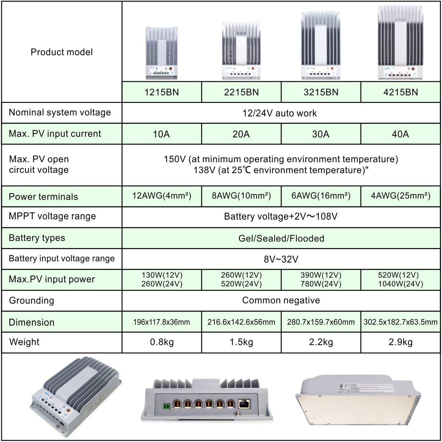
Figure 9.1: Comparison table of EPEVER Tracer BN series models. This table provides a side-by-side comparison of different models (1215BN, 2215BN, 3215BN, 4215BN) across various specifications such as nominal system voltage, max PV input current, max PV open circuit voltage, power terminals, MPPT voltage range, battery types, battery input voltage range, max PV input power, grounding, dimension, and weight. The Tracer2215BN is highlighted within this series.
10. Maintenance
Regular maintenance ensures the longevity and optimal performance of your solar charge controller:
- Check Connections: Periodically inspect all wiring connections for tightness and corrosion. Loose connections can cause overheating and power loss.
- Clean Controller: Keep the controller clean and free from dust and debris. Ensure the heat sink fins are not obstructed to maintain proper cooling.
- Inspect for Damage: Check for any physical damage to the casing, cables, or terminals.
- Battery Health: Monitor battery voltage and health. Ensure the battery type setting in the controller matches your battery.
- Environmental Conditions: Ensure the installation environment remains within the specified operating temperature and humidity ranges.
11. Troubleshooting
This section addresses common issues you might encounter with your Tracer2215BN controller.
| Problem | Possible Cause | Solution |
|---|---|---|
| No charging from PV |
|
|
| Load not working |
|
|
| Controller overheating |
|
|
12. Warranty and Support
For warranty information and technical support, please contact the authorized seller or EPEVER customer service. GolandCentury is an authorized sales agent for EPEVER products and offers technical support through their service centers located in Chicago (USA), Munich (Germany), Toronto (Canada), and Melbourne (Australia).
Please retain your purchase receipt for warranty claims.