
1. Introduction
The Akozon TS-FT002 is an ultrasonic water level sensor designed to monitor the liquid depth in a tank and display it on a 10-element liquid crystal bar graph. This device also provides simultaneous indoor and tank temperature readings. It supports high/low liquid level alarms and an empty tank alert, offering convenient monitoring for various non-corrosive liquid storage applications.
2. Product Features
- Monitors liquid depth in tanks and displays it on a 10-element LCD bar graph.
- Records minimum and maximum liquid levels.
- Features high/low liquid level alarms and an empty tank alert.
- Displays both indoor temperature and tank temperature concurrently.
- The receiver unit can be placed on a desk or mounted on a wall.
3. Package Contents
Please check the package for the following items:
- 1 x Ultrasonic Water Level Sensor (Transmitter)
- 1 x Indoor Receiver Display Unit
- 2 x Mounting Screws
Note: Batteries are not included. Please prepare 2 x AA 1.5V alkaline batteries for the receiver and 6 x AAA 1.5V lithium batteries for the transmitter.
4. Specifications
| Feature | Specification |
|---|---|
| Indoor Temperature Range | 0 ~ 60 °C |
| Outdoor Temperature Range | -40 ~ 60 °C |
| Temperature Accuracy | ± 1 °C |
| Water Level Measurement Range | 0 ~ 15 m |
| Water Level Resolution | 0.01 m |
| Water Level Accuracy | +/- 0.03 m |
| Transmission Frequency | 433 MHz |
| Transmission Distance | 100 m (in open area) |
| Transmission Interval | 30 seconds (level change) / 3 minutes (level stable) |
| Receiver Battery | 2 x AA 1.5V LR3 Alkaline (not included) |
| Transmitter Battery | 6 x AAA 1.5V LR6 Lithium (not included) |
| Receiver Battery Life | Approx. 12 months |
| Transmitter Battery Life | Minimum 12 months |
| Receiver Dimensions | 108 x 94 x 27 mm |
| Transmitter Dimensions | 97 x 68 x 152 mm |
| LCD Screen Size | 66 x 45 mm |
| Suitable Liquids | Any non-corrosive liquid |
| Mounting | Receiver: Desk-standing or Wall-mount |
| Sensor Technology | Ultrasonic |
5. Component Overview
Receiver Display with Labeled Components
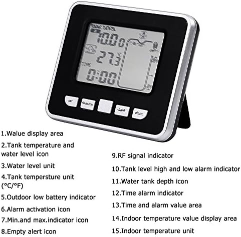
This image shows the receiver unit's display with various indicators and buttons labeled for easy identification.
- Value display area
- Tank temperature and water level icon
- Water level unit
- Tank temperature unit (°C/°F)
- Outdoor low battery indicator
- Alarm activation icon
- Min. and max. indicator icon
- Empty alert icon
- RF signal indicator
- Tank level high and low alarm indicator
- Water tank depth icon
- Time alarm indicator
- Time and alarm value area
- Indoor temperature value display area
- Indoor temperature unit
Detailed LCD Display Description

This diagram provides a comprehensive breakdown of all indicators and segments on the LCD screen.
- Tank Level Display
- Feet/Meters Unit
- Temperature Unit (°C/°F)
- High Alarm Indicator
- Low Alarm Indicator
- RF Signal Strength
- Min/Max Record Indicator
- Empty Tank Alert
- Full Tank Indicator
- 10-Segment Bar Graph for Water Level
- Water Level Percentage
- Time Display
- AM/PM Indicator
- Indoor Temperature Display
- Indoor Temperature Unit (°C/°F)
- Home Icon (Indoor)
Sensor and Receiver Units
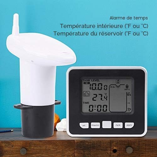
This image displays the complete Akozon TS-FT002 system, showing the ultrasonic sensor (transmitter) and the indoor receiver unit.
Sensor Installation Example
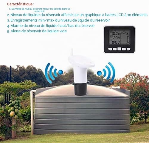
An illustration of the ultrasonic sensor correctly installed on a water tank, demonstrating its wireless communication with the receiver unit.
Sensor Balance Bubble

A close-up of the ultrasonic sensor's top, highlighting the integrated balance bubble to ensure a level and accurate installation.
Receiver Rear View

The back of the receiver unit, showing the battery compartment cover, wall-mounting slots, and product information including the model number TS-FT002.
Product Dimensions

This image provides the physical dimensions of both the ultrasonic sensor (transmitter) and the receiver unit for installation planning.
Installation Sketch and Examples

A detailed diagram showing the correct method for installing the transmitter, along with visual examples of common incorrect installation scenarios to avoid.
6. Setup Instructions
6.1. Battery Installation
- Receiver Unit: Open the battery compartment on the back of the receiver. Insert 2 x AA 1.5V alkaline batteries, ensuring correct polarity. Close the compartment.
- Transmitter Unit (Sensor): Open the battery compartment on the sensor unit. Insert 6 x AAA 1.5V lithium batteries, observing correct polarity. Close the compartment securely to maintain water resistance.
6.2. Transmitter (Sensor) Installation
The transmitter should be installed on top of the tank, directly above the liquid surface, ensuring a clear path for the ultrasonic signal. Refer to the 'Installation Sketch and Examples' image for visual guidance.
- Location: Choose a location on the tank where the sensor can be mounted vertically and stably. Avoid areas with obstructions directly below the sensor that could interfere with the ultrasonic beam.
- Leveling: Use the integrated balance bubble on the top of the sensor to ensure it is perfectly level. An unlevel installation can lead to inaccurate readings.
- Clearance: Ensure there is at least 0.5 meters (H1) of clear space between the sensor and the maximum liquid level. The sensor should also be at least 20 cm (R) away from the tank walls or any internal structures to prevent false readings.
- Mounting: Secure the transmitter using the provided screws or other suitable mounting hardware. Ensure it is firmly attached and will not shift.
- Liquid Type: This sensor is suitable for any non-corrosive liquid. Do not use with corrosive substances.
6.3. Receiver Unit Placement
Place the receiver unit indoors within the 100-meter transmission range of the transmitter. Consider the following:
- Signal Strength: Position the receiver where it can receive a strong RF signal from the transmitter. Walls and other obstacles can reduce the effective range.
- Visibility: Place the receiver in a location where the display is easily visible for monitoring.
- Mounting: The receiver can stand on a flat surface (e.g., desk) using its integrated stand or be mounted on a wall using the slots on its back.
7. Operating Instructions
7.1. Initial Power-On and Synchronization
Once batteries are installed in both units, they should automatically attempt to synchronize. The receiver's display will show the current liquid level and temperatures after successful synchronization.
7.2. Display Readings
The LCD display provides the following information:
- Liquid Level: Shown as a numerical value (in meters) and a 10-segment bar graph.
- Tank Temperature: The temperature of the liquid in the tank.
- Indoor Temperature: The ambient temperature at the receiver's location.
- Time: Current time display.
- RF Signal Indicator: Shows the strength of the wireless connection.
- Battery Indicators: Alerts for low battery in either the receiver or transmitter.
7.3. Setting Alarms
The device allows setting high and low liquid level alarms, as well as an empty tank alert. Refer to the receiver's buttons (SET, MAX/MIN, TANK, ALARM) for navigation and adjustment. Detailed programming steps are typically found in the full product manual, but generally involve:
- Pressing the ALARM button to cycle through alarm settings.
- Using SET or other navigation buttons to adjust the desired high/low level thresholds.
- Confirming settings to activate the alarms.
7.4. Min/Max Records
The device automatically records the minimum and maximum liquid levels. Press the MAX/MIN button to view these recorded values.
8. Maintenance
- Battery Replacement: Replace batteries in both the receiver and transmitter units when the low battery indicator appears on the display. Ensure to use the specified battery types (AA for receiver, AAA for transmitter).
- Cleaning: Wipe the receiver display and sensor unit with a soft, dry cloth. Do not use abrasive cleaners or immerse the units in water.
- Sensor Check: Periodically inspect the transmitter unit for any debris or buildup that might obstruct the ultrasonic sensor. Clean gently if necessary.
- Environmental Conditions: Ensure the transmitter is not exposed to extreme conditions beyond its operating temperature range (-40 ~ 60 °C) or corrosive environments.
9. Troubleshooting
- No Display/Power: Check if batteries are correctly installed and have sufficient charge. Replace if necessary.
- No Signal/Inaccurate Readings:
- Ensure the transmitter and receiver are within the 100m range and there are no major obstructions (e.g., thick walls) between them.
- Verify the transmitter is installed level using the balance bubble.
- Check for obstructions directly below the sensor inside the tank.
- Ensure the sensor is not too close to the tank walls (minimum 20cm clearance).
- Confirm the liquid is non-corrosive.
- If the tank has a high dome (e.g., 60cm), ensure the sensor is positioned correctly to avoid measuring the tank entrance rim instead of the liquid surface.
- Difficulty with Programming/Settings: The programming interface can be complex. Refer to the detailed instructions in the complete product manual for specific button sequences and menu options.
- Alarms Not Triggering: Check that the high/low alarm thresholds are set correctly and are within the expected operating range.
10. Warranty and Support
For warranty information and technical support, please refer to the documentation provided with your purchase or contact Akozon customer service through their official channels. Keep your purchase receipt as proof of purchase.