
AOPUTTRIVER AP-570C
AOPUTTRIVER AP-570C Digital Clamp Meter Multimeter User Manual
Model: AP-570C
1. Introduction
The AOPUTTRIVER AP-570C is a 4000-count auto-ranging digital clamp meter designed for precise electrical measurements. It offers a wide range of functions including AC/DC current, AC/DC voltage, resistance, capacitance, frequency, duty cycle, temperature, diode test, and continuity. This manual provides essential information for safe and effective operation of your device.
2. Safety Information
Always adhere to safety precautions when using electrical testing equipment. Failure to do so may result in electric shock, injury, or damage to the meter or equipment under test.
- Ensure the meter is in good working condition before use.
- Do not apply voltage or current exceeding the maximum rated values.
- Use appropriate personal protective equipment (PPE) such as insulated gloves and safety glasses.
- Verify the function switch is in the correct position for the measurement being performed.
- Avoid touching exposed conductors or circuit components during measurements.
- Do not operate the meter in wet environments or in the presence of explosive gases or dust.
- Replace batteries promptly when the low battery indicator appears to ensure accurate readings.
- The AP-570C Clamp Meter meets IEC1010 Double Insulation, Pollution Degree 2, and Overvoltage Category III standards.
3. Product Components
The AOPUTTRIVER AP-570C package includes the following items:
- AOPUTTRIVER AP-570C Clamp Meter
- Test Leads (2)
- Temperature Probe
- 9V (6F22) Battery
- User Manual
- Storage Bag
- Small Screwdriver

Image: AOPUTTRIVER AP-570C Digital Clamp Meter with test leads, temperature probe, battery, and storage bag.
4. Product Diagram and Key Functions
Familiarize yourself with the main parts and controls of the AP-570C clamp meter:

Image: Labeled diagram of the AP-570C showing the clamp, rotary switch, LCD display, D.HOLD/Back Light key, SELECT key, MAX/MIN key, REL key, Hz/DUTY key, COM Input Jack, and T+VΩHz Input Jack.
- Clamp: Used for non-contact AC/DC current measurement.
- Rotary Switch: Selects the desired measurement function.
- LCD Display: Shows measurement readings and indicators.
- D.HOLD/Back Light Key: Freezes the current reading on the display and activates/deactivates the backlight.
- SELECT Key: Toggles between different measurement modes within a single rotary switch position (e.g., AC/DC voltage, diode/continuity).
- MAX/MIN Key: Records maximum and minimum values during a measurement session.
- REL Key: Activates relative measurement mode.
- Hz/DUTY Key: Selects frequency or duty cycle measurement.
- Input Jacks (COM, T+VΩHz): Connect test leads for voltage, resistance, capacitance, diode, continuity, and temperature measurements.
5. Setup
5.1. Battery Installation
The AP-570C requires one 9V (6F22) battery. To install or replace the battery:
- Ensure the meter is turned OFF.
- Use the provided small screwdriver to open the battery compartment cover on the back of the meter.
- Insert the 9V battery, observing the correct polarity (+/-).
- Replace the battery compartment cover and secure it with the screw.
5.2. Connecting Test Leads
For most measurements (voltage, resistance, capacitance, diode, continuity, temperature), connect the test leads:
- Insert the black test lead into the "COM" (common) input jack.
- Insert the red test lead into the "T+VΩHz" input jack.
- For temperature measurements, connect the temperature probe to the same input jacks, ensuring correct polarity if applicable.
6. Operating Instructions
6.1. AC/DC Current Measurement (Clamp)
The clamp function allows for non-contact current measurement. This is ideal for safely measuring current in live circuits.
- Turn the rotary switch to the desired current range (e.g., 400A or 1000A).
- Press the SELECT button to toggle between AC and DC current measurement if necessary.
- Open the clamp jaws by pressing the trigger.
- Enclose a single conductor (not a bundle of wires) within the clamp jaws. Ensure the jaws are fully closed.
- Read the current value on the LCD display.

Image: The AP-570C clamp meter measuring current on an electrical cable.
Video: Demonstration on how to measure DC current using a clamp meter.
6.2. AC/DC Voltage Measurement
To measure voltage, use the test leads connected to the appropriate input jacks.
- Turn the rotary switch to the "V~" (AC Voltage) or "V-" (DC Voltage) position. The meter may auto-range.
- Connect the test leads in parallel to the circuit or component you wish to measure.
- Read the voltage value on the LCD display.

Image: The AP-570C clamp meter with test leads connected to an electrical outlet for voltage measurement.
6.3. Resistance, Capacitance, Diode, and Continuity Measurement
These functions are accessed via the rotary switch and SELECT button.
- Turn the rotary switch to the "Ω" (Resistance), "CAP" (Capacitance), or "Diode/Continuity" position.
- Use the SELECT button to switch between Diode Test and Continuity Test if on the combined setting.
- Connect the test leads across the component to be measured.
- Read the value on the LCD display. For continuity, a buzzer will sound if continuity is detected.
Video: Demonstration on how to measure capacitance using a clamp meter.
6.4. Temperature Measurement
The AP-570C can measure temperature using the included temperature probe.
- Turn the rotary switch to the "°C" (Temperature) position.
- Connect the temperature probe to the "COM" and "T+VΩHz" input jacks.
- Place the tip of the temperature probe on or in the object whose temperature you wish to measure.
- Read the temperature value on the LCD display. The range is -20°C to 1000°C.
6.5. Backlight and Data Hold
- Backlight: Press the "D.HOLD/Back Light" button briefly to turn the LCD backlight on or off, improving visibility in low-light conditions.
- Data Hold: Press and hold the "D.HOLD/Back Light" button to freeze the current reading on the display. Press again to release.

Image: Close-up view of the AP-570C's bright LCD display and protective case.
6.6. Non-Contact Voltage (NCV) Detection
The NCV function allows for quick detection of AC voltage without direct contact.
- Turn the rotary switch to the "NCV" position.
- Move the top part of the meter (near the clamp jaws) close to the conductor or outlet.
- The meter will indicate the presence of AC voltage through an audible beep and/or visual indicator.
7. Specifications
Key technical specifications for the AOPUTTRIVER AP-570C:
- Display: 4000 Counts
- DC Current: 200A~1000A
- AC Current: 400A~1000A (0.1A resolution for 0.1~400A)
- DC Voltage: 400mV~1000V
- AC Voltage: 4V~750V
- Resistance: 400Ω, 4KΩ, 40KΩ, 400KΩ, 4MΩ, 40MΩ
- Capacitance: 5.12nF~100µF
- Frequency: Yes
- Duty Cycle: Yes
- Diode Test: Yes
- Continuity Buzzer: Yes
- Temperature Range: -20°C to 1000°C
- Jaw Caliber: 45mm (1.77 in)
- Safety Rating: IEC1010 Double Insulation, Pollution Degree 2, Overvoltage Category III
- Power Source: 1 x 9V battery (included)
- Product Dimensions: 22.35 x 9.65 x 3.81 cm
- Item Weight: 444.52 g (0.98 Pounds)
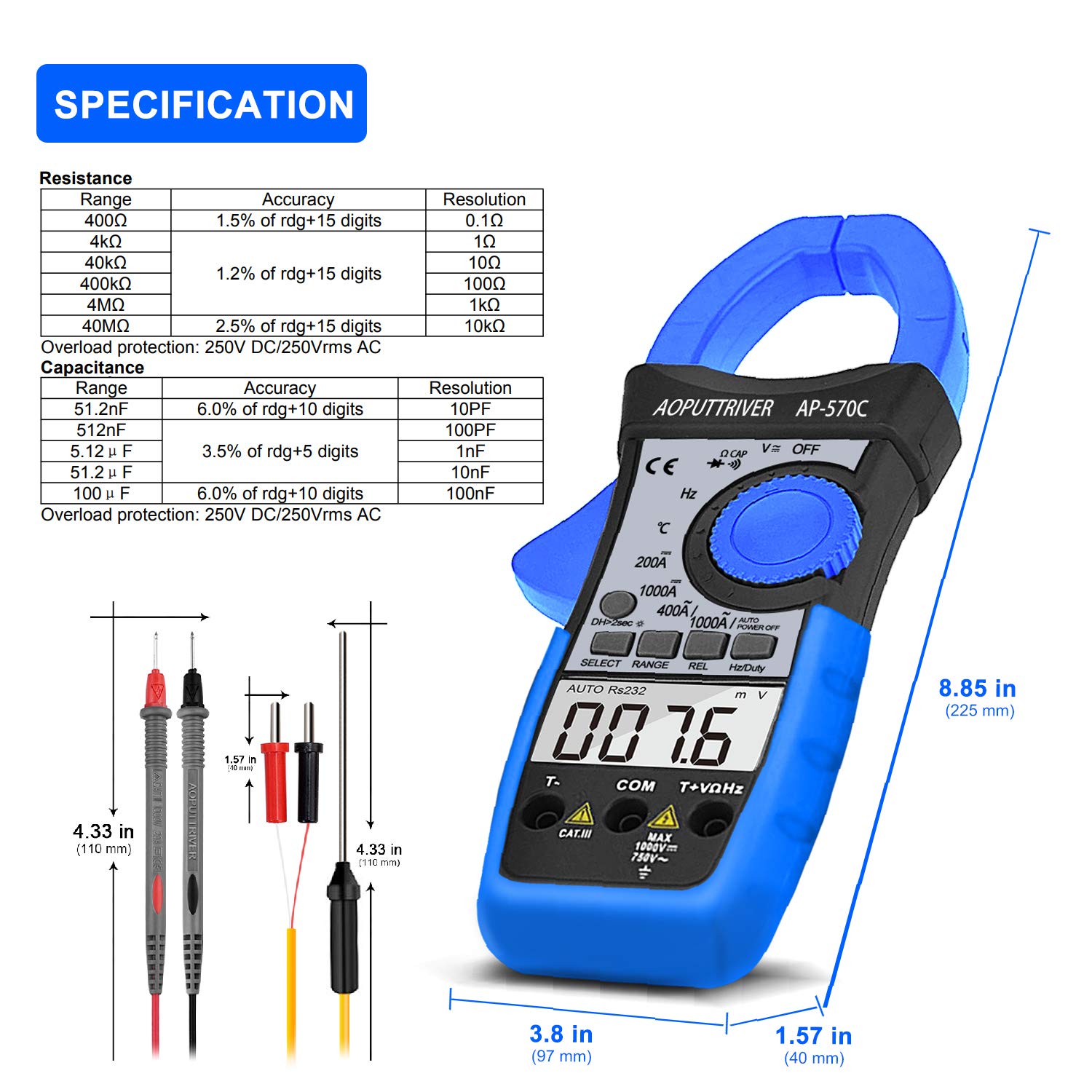
Image: Detailed specifications table for Resistance and Capacitance, along with physical dimensions of the meter and test leads.
8. Maintenance
8.1. Cleaning
To maintain the accuracy and longevity of your meter:
- Wipe the case with a damp cloth and mild detergent. Do not use abrasives or solvents.
- Keep the input terminals and clamp jaws clean and free of debris.
8.2. Battery Replacement
When the low battery indicator appears on the LCD, replace the 9V battery as described in the "Setup" section. Prompt replacement ensures continued accuracy.
8.3. Storage
When not in use, store the meter in its protective storage bag in a dry, cool place, away from direct sunlight and extreme temperatures.
9. Troubleshooting
If you encounter issues with your AP-570C, consider the following common solutions:
- No Display/Faint Display: Check battery charge and ensure it is correctly installed. Replace if necessary.
- "OL" on Display: Indicates an over-range condition. The measured value exceeds the selected range. Switch to a higher range or verify the circuit.
- Inaccurate Readings:
- Ensure test leads are fully inserted and making good contact.
- Verify the rotary switch is set to the correct function and range.
- For current measurements, ensure only one conductor is within the clamp jaws.
- Check for external electromagnetic interference.
- Continuity Buzzer Not Working: Ensure the meter is in continuity mode and test leads are making proper contact. If the issue persists, the meter may require service.
10. Warranty and Support
The AOPUTTRIVER AP-570C comes with a 2-year warranty and lifetime technical support. For any questions or assistance with your product, please contact AOPUTTRIVER customer support.
You can visit the official AOPUTTRIVER store for more information: AOPUTTRIVER Store
Related documentsAP-570C


Ask a question about this manual
Ask about setup, troubleshooting, compatibility, parts, safety, or missing instructions. Manuals+ will review the question and use this page’s manual context to help answer it.