
EPEVER GM3024N
EPEVER GM3024N Solar Charge Controller User Manual
Model: GM3024N
1. Product Overview
The EPEVER GM3024N is a flush-mounted 30A 12V/24V auto-work negative-ground solar charge controller. It utilizes Pulse Width Modulated (PWM) charging mode and is designed for off-grid solar systems, including applications in Recreation Vehicles (RVs), mobile service vehicles, and solar boats.
Key features of the GM3024N include:
- Flush mounted and embedded installation design.
- High quality and low failure rate components (ST/IR) for extended product lifetime.
- 3-Stage intelligent PWM charging: Bulk, Boost/Equalize, and Float.
- Compatibility with Sealed, Gel, and Flooded lead-acid batteries, with a user-definable option.
- Real-time energy statistics feature.
- Battery temperature compensation feature.
- Digital LCD monitor for displaying operational parameters and fault messages.
- RS485 communication port with Modbus protocol, offering short circuit protection for 5V/200mA power supply.
- Multiple communication peripherals for monitoring and setting parameters via PC software or mobile app.
- Rated charging current at working temperature without de-rating.
- Extensive electronic protections against overcharging, overload, short-circuit, and reverse polarity.

Figure 1: Front view of the EPEVER GM3024N Solar Charge Controller, showing the LCD display and control buttons.
2. Product Components and Exterior
The GM3024N controller features a compact design with clearly labeled components for easy installation and operation.
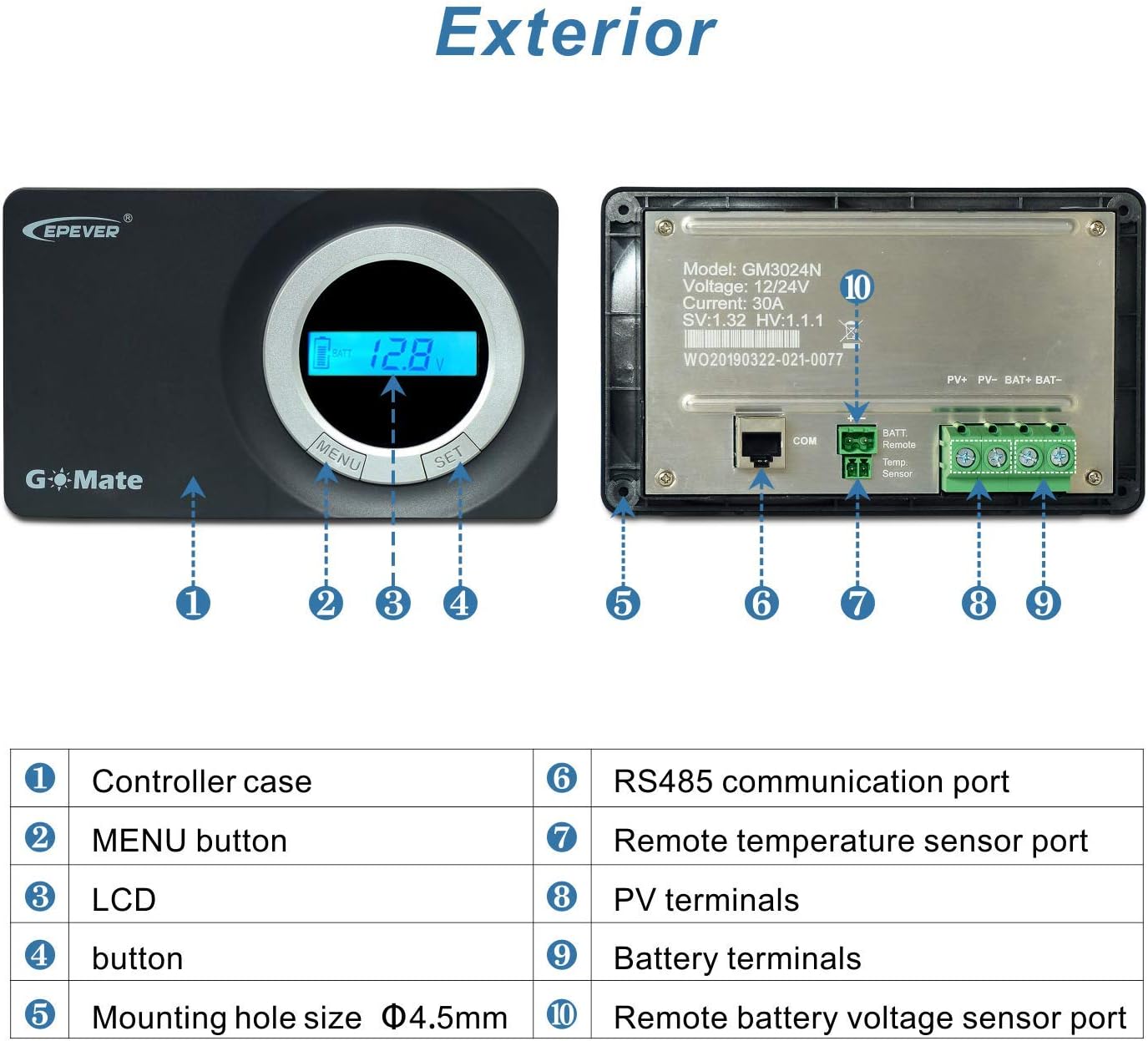
Figure 2: Exterior view and component identification of the GM3024N controller.
- Controller case: The main housing of the device.
- MENU button: Used to navigate through display menus and settings.
- LCD: Liquid Crystal Display for showing operational data and fault messages.
- SET button: Used to confirm selections and adjust parameters.
- Mounting hole size: Φ4.5mm holes for secure installation.
- RS485 communication port: For connecting to PC software, mobile app, or other communication peripherals.
- Remote temperature sensor port: For connecting an external temperature sensor to enable battery temperature compensation.
- PV terminals: Connections for solar panel input.
- Battery terminals: Connections for battery bank.
- Remote battery voltage sensor port: For connecting an external voltage sensor for more accurate battery voltage readings.
3. Setup and Installation
The GM3024N is designed for flush-mounted and embedded installation. Ensure the installation location is well-ventilated and protected from direct sunlight, high temperatures, and moisture.
3.1 Wiring Connections
Follow the connection sequence carefully to prevent damage to the controller or other components. The controller is a common-negative ground type.

Figure 3: Wiring diagram for the GM3024N controller.
- Connect the Battery: Connect the battery to the controller's battery terminals. Ensure correct polarity. The controller will detect the battery voltage (12V or 24V) automatically.
- Connect the Solar Panel: Connect the solar panel to the controller's PV terminals. Ensure correct polarity.
- Connect Remote Sensors (Optional): If using, connect the remote battery voltage sensor and remote temperature sensor to their respective ports. These enhance charging accuracy.
- Connect Communication Peripherals (Optional): Connect PC, mobile app (via Bluetooth/Wi-Fi module), or MT50 remote meter to the RS485 communication port for monitoring and parameter setting.
Recommended Cable Size: The controller terminals support up to 16mm² (6AWG) wire. For optimal performance, a recommended cable size of 10mm² (8AWG) is suggested for connections.
3.2 Battery Type Selection
The controller is compatible with Sealed, Gel, and Flooded lead-acid batteries. A 'User' defined battery type is also available for custom settings. Ensure the correct battery type is selected in the controller settings to optimize charging and prolong battery life.
4. Operating Instructions
The GM3024N features an intuitive LCD display for real-time monitoring and parameter adjustment.
4.1 LCD Display and Buttons
The LCD displays various operational parameters such as PV voltage, PV current, PV power, battery voltage, and battery temperature. Fault messages are also shown on the display.
- MENU Button: Press to cycle through different display screens and enter setting menus.
- SET Button: Press to confirm selections or modify parameters within a setting menu.
4.2 Charging Process
The controller employs a 3-stage intelligent PWM charging algorithm:
- Bulk Charge: Charges the battery at maximum current until the voltage reaches the Boost voltage setpoint.
- Boost/Equalize Charge: Charges at a higher voltage for a set period to ensure the battery is fully charged and to equalize cell voltages (for flooded batteries).
- Float Charge: Maintains the battery at a lower voltage to prevent self-discharge and keep it fully charged.
4.3 Parameter Setting and Monitoring
Parameters can be monitored and set using the built-in LCD and buttons, or through external communication methods:
- PC Software: Connect the controller to a computer via the RS485 port for detailed monitoring and configuration.
- Mobile App: Use a compatible Bluetooth or Wi-Fi module (sold separately) to connect to a smartphone app for remote monitoring and control.
- MT50 Remote Meter: An optional external display unit that provides comprehensive control and monitoring capabilities.
5. Maintenance
Regular maintenance ensures the longevity and optimal performance of your EPEVER GM3024N solar charge controller.
- Cleanliness: Keep the controller clean and free from dust and debris. Use a dry cloth for cleaning.
- Connections: Periodically check all wiring connections to ensure they are tight and secure. Loose connections can cause overheating or poor performance.
- Inspection: Inspect the controller and wiring for any signs of damage, corrosion, or wear. Address any issues promptly.
- Ventilation: Ensure that the area around the controller remains well-ventilated to prevent overheating.
6. Troubleshooting
The GM3024N is equipped with extensive electronic protections and can display fault messages on its LCD. Refer to the display for error codes or indicators.
Common Issues and Solutions:
- No Display/Power:
- Check battery connections and ensure correct polarity.
- Verify battery voltage is within the operating range (9V~32V).
- No Charging:
- Check solar panel connections and ensure correct polarity.
- Verify solar panel voltage is sufficient (Max.PV open circuit voltage: 50VDC).
- Ensure there is adequate sunlight on the solar panels.
- Overcharge/Over-discharge Protection:
- The controller automatically protects against these conditions. If charging stops, check battery health and settings.
- Ensure the correct battery type is selected.
- Fault Messages on LCD:
- Consult the detailed user manual (typically provided with the product) for specific error code interpretations and troubleshooting steps.
- Common protections include overcharging, overload, short-circuit, and reverse polarity.
For persistent issues or complex problems, contact EPEVER customer support or refer to the comprehensive manual that came with your product.
7. Specifications
Detailed technical specifications for the EPEVER GM3024N Solar Charge Controller:

Figure 4: Technical specifications of the GM3024N controller.
| Electrical Parameters | |
|---|---|
| Nominal System Voltage | 12/24VDC or Auto |
| Battery Input Voltage Range | 8V ~ 32V |
| Rated Charge Current | 30A |
| Max. PV Short Circuit Current | 30A |
| Max. PV Open Circuit Voltage | 50VDC (48V at 25℃ temperature) |
| Battery Type | Sealed (default)/Gel/Flooded/User |
| Self-consumption | ≤4.2mA/12V; ≤2.6mA/24V |
| Temperature Compensation Coefficient | -3mV/℃/2V (Default) |
| Charge Circuit Voltage Drop | 0.21V |
| Environmental Parameters | |
| Storage Temperature Range | -30℃ ~ +80℃ |
| Working Environment Temperature | -20℃ ~ +55℃ (100% input and output) |
| Relative Humidity | ≤95%, N.C. |
| Enclosure | IP30 |
| Grounding | Common negative |
| Altitude | 5000m |
| Pollution Degree | PD2 |
| Mechanical Parameters | |
| Dimension (L×W×H) | 178.5×105.5×48.3mm |
| Mounting Dimension | 166.5×93.5mm |
| Mounting Hole Size | Φ5mm |
| Terminal | 16mm² / 6AWG |
| Recommended Cable | 10mm² / 8AWG |
| Net Weight | 0.31kg |
Note: The battery type of 'User' can be set via PC software, APP software, and MT50.

Figure 5: Product packaging dimensions.
8. Warranty and Support
Specific warranty terms and conditions for the EPEVER GM3024N Solar Charge Controller are typically provided with the product packaging or available on the manufacturer's official website. Please retain your proof of purchase for warranty claims.
For technical support, troubleshooting assistance, or further inquiries, please visit the official EPEVER website or contact their customer service department. You can also visit the EPEVER Store on Amazon for more information and product resources.
Ask a question about this manual
Ask about setup, troubleshooting, compatibility, parts, safety, or missing instructions. Manuals+ will review the question and use this page’s manual context to help answer it.