1. Introduction
This manual provides detailed instructions for the installation, operation, and maintenance of your GAMEMAX G510 Optical Computer Chassis. Please read this guide thoroughly before beginning assembly to ensure proper setup and to maximize the performance and longevity of your system. The GAMEMAX G510 is a mid-tower chassis designed for Micro ATX motherboards, featuring an optical design with transparent panels and support for efficient air cooling.
2. Product Overview
The GAMEMAX G510 Optical Computer Chassis is engineered to provide a visually striking and functional housing for your computer components. It features tempered glass panels for showcasing your build and optimized airflow for cooling.
2.1 Chassis Features
- Mid-Tower Design: Compatible with Micro ATX motherboards.
- Optical Front Panel: Enhances aesthetic appeal with transparent elements.
- Tempered Glass Side Panel: Provides a clear view of internal components.
- Efficient Cooling Support: Designed for optimal air cooling with multiple fan mounts.
- Cable Management: Features for neat and organized cable routing.

Front and side view of the GAMEMAX G510 chassis, highlighting the transparent front panel and side tempered glass, showcasing the pre-installed RGB fans.
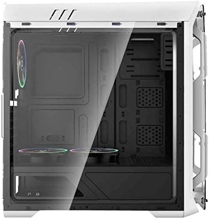
An internal view of the GAMEMAX G510 chassis, illustrating the spacious interior for component installation, including the motherboard tray and cutouts for cable management.
3. Setup and Component Installation
Before beginning, ensure you have all necessary components and tools, including a Phillips head screwdriver, zip ties, and anti-static precautions.
3.1 Preparing the Chassis
- Carefully unbox the chassis and remove all packaging materials.
- Place the chassis on a stable, flat surface.
- Remove the tempered glass side panel by unscrewing the thumb screws and gently pulling it away. Set it aside on a soft, non-abrasive surface.
- Remove the opposite metal side panel by unscrewing the thumb screws at the rear and sliding it backward.
3.2 Motherboard Installation
The GAMEMAX G510 supports Micro ATX motherboards.
- Install the I/O shield into the cutout at the rear of the chassis.
- Ensure the standoffs for your Micro ATX motherboard are correctly aligned and tightened. If necessary, install additional standoffs provided with the chassis.
- Carefully place your motherboard onto the standoffs, aligning the screw holes.
- Secure the motherboard with the appropriate screws. Do not overtighten.

Detailed interior shot of the GAMEMAX G510, showing the layout for storage drives and the power supply shroud area, designed for clean builds.
3.3 Power Supply Unit (PSU) Installation
The GAMEMAX G510 does not include a power supply.
- Locate the PSU mounting area at the bottom rear of the chassis.
- Slide your PSU into the designated bay from the rear of the chassis.
- Align the screw holes and secure the PSU with the screws provided with your power supply.
3.4 Storage Drive Installation (HDD/SSD)
Refer to the chassis interior for specific drive bay locations.
- 3.5" HDDs: Typically installed in drive cages located under the PSU shroud or behind the motherboard tray. Secure with screws or tool-less mechanisms.
- 2.5" SSDs: Often mounted on dedicated brackets behind the motherboard tray or on the PSU shroud. Secure with screws.
3.5 Expansion Card Installation (GPU, PCIe Cards)
- Remove the necessary expansion slot covers from the rear of the chassis.
- Insert your expansion card (e.g., graphics card) into the corresponding PCIe slot on your motherboard.
- Secure the card to the chassis with the provided screw or retention clip.

Rear perspective of the GAMEMAX G510 chassis, displaying the rear exhaust fan mount, motherboard I/O shield cutout, and expansion slots for graphics cards and other PCIe devices.
3.6 Fan and Cooling Installation
The G510 supports 120mm fans for air cooling.
- Identify available fan mounting points (front, top, rear).
- Mount your 120mm fans using the provided fan screws. Ensure correct airflow direction (intake or exhaust).
- Connect fan power cables to your motherboard or a fan controller.
3.7 Cable Management
Utilize the cable routing cutouts and tie-down points behind the motherboard tray to organize cables. This improves airflow and aesthetics.
- Route all necessary cables (24-pin ATX, 8-pin EPS, SATA, PCIe power, front panel connectors) through the cutouts.
- Use zip ties or Velcro straps to bundle and secure cables.
- Connect front panel cables (USB, audio, power/reset switches, LED indicators) to the appropriate headers on your motherboard. Refer to your motherboard manual for specific pinouts.

Side view of the GAMEMAX G510 chassis with the tempered glass panel removed, revealing the internal structure and mounting points for components.
4. Operating Your System
Once all components are installed and cables are connected, you can power on your system.
- Ensure all external peripherals (monitor, keyboard, mouse) are connected.
- Connect the power cable to your PSU and a wall outlet.
- Flip the power switch on your PSU to the 'ON' position.
- Press the power button on the front panel of your GAMEMAX G510 chassis.
The pre-installed fans will illuminate and begin spinning, indicating power is supplied. Monitor your system during initial boot-up for any unusual noises or errors.
5. Maintenance
Regular maintenance helps ensure optimal performance and extends the lifespan of your computer components.
- Dust Filters: Periodically check and clean any removable dust filters (e.g., front, top, bottom). Use compressed air or wash with water and allow to dry completely before reinstallation.
- Interior Cleaning: Use compressed air to remove dust buildup from fans, heatsinks, and other components inside the chassis. Perform this in a well-ventilated area.
- Exterior Cleaning: Wipe down the exterior surfaces, including tempered glass panels, with a soft, damp cloth. Avoid harsh chemicals.
6. Troubleshooting
If you encounter issues, consider the following basic troubleshooting steps:
- No Power: Ensure the PSU is switched on, the power cable is securely connected, and the front panel power button cable is correctly attached to the motherboard.
- Fans Not Spinning: Check that all fan power cables are securely connected to the motherboard or fan controller.
- No Display: Verify that your monitor is connected to the graphics card (not the motherboard I/O unless using integrated graphics) and that the graphics card is properly seated and powered.
- Unusual Noises: Inspect fans for obstructions or loose cables.
For more complex issues, consult your individual component manuals or seek professional assistance.
7. Specifications
| Feature | Specification |
|---|---|
| Brand | GAMEMAX |
| Model Number | G510 |
| Manufacturer Number | 18814g510wt00165 |
| Type | Mid Tower |
| Color | White |
| Motherboard Compatibility | Micro ATX |
| Power Supply Included | No |
| Cooling Method | Air |
| Fan Size Support | 120 Millimeters |
| Item Weight | 13.1 Pounds (5.94 kg) |
| Package Dimensions | 55.2 x 50.2 x 24.2 cm |
8. Safety Information
- Always disconnect the power cable from the wall outlet before opening the chassis or performing any maintenance.
- Handle tempered glass panels with care to prevent breakage.
- Use anti-static precautions (e.g., anti-static wrist strap) when handling internal components to prevent electrostatic discharge (ESD) damage.
- Keep small parts and screws away from children.
9. Warranty and Support
For warranty information and technical support, please refer to the documentation provided with your purchase or visit the official GAMEMAX website. Keep your proof of purchase for warranty claims.


