
1. Introduction
This manual provides essential information for the safe and efficient operation of the YWBL-WH SKI780 Mini VFD Frequency Converter. This device is designed to convert single-phase 220V AC power to three-phase 220V AC power, enabling control of 2.2kW motors. Please read this manual thoroughly before installation, operation, or maintenance to ensure proper usage and prevent potential hazards.
The SKI780 features V/F control, vector control, and output torque control. It includes a speed potentiometer and an external panel for user interaction, offering 6 speed control modes for automatic operation. Integrated communication, synchronous control, proportional timing control, a user-defined counter/timer, and a PID regulation function facilitate closed-loop control of temperature, pressure, and voltage.
2. Safety Precautions
WARNING: Failure to follow these safety instructions may result in electric shock, injury, or equipment damage.
- Installation and operation must be performed by qualified professionals.
- Do not connect wiring when the power supply is turned on. This can cause electrical shock or injury.
- Ensure correct terminal voltage and polarity to prevent damage to the equipment or injury to personnel.
- Avoid routing power lines and signal lines through the same conduit or tying them together to prevent interference.
- The frequency inverter must be matched with an asynchronous motor. Ensure good heat dissipation conditions during operation.
- Do not touch the heat sink or brake resistor of the inverter while it is running, as they can be extremely hot and cause burns.
- Avoid frequent power supply switching. It is recommended to maintain a control interval of at least 1 minute.
- Connecting the AC power supply to the output terminals (U, V, W) of the frequency inverter is strictly prohibited, as this will cause internal damage to the unit.

3. Product Overview
3.1 Appearance and Dimensions


3.2 Control Panel and Indicators

The control panel features a digital display and several buttons for programming and operation. Key indicators include:
- RUN: Indicates the AC drive is in the running state (ON) or stop state (OFF).
- LOC: Indicates whether the AC drive is operated via the operation panel, terminals, or communication.
- F/R: Indicates reverse rotation.
- Hz, A, V: Unit Indicators. These indicate the temporary display unit.
- Hz: Unit of frequency
- A: Unit of current
- V: Unit of voltage
- Hz + A: Unit of rotational speed
- A + V: Percentage
3.3 Model Designation Rules

The model number SKI780-2D2G-1 can be broken down as follows:
- SKI780: Model series.
- 2D2: Power rating. 0D75 = 0.75kW, 1D5 = 1.5kW, 2D2 = 2.2kW.
- G: General purpose.
- 1: Input Level. 1 = 1 phase 220V, 4 = 3 phase 380V.
4. Specifications
| Parameter | Value |
|---|---|
| Model Name | SKI780 |
| Brand | YWBL-WH |
| Recommended Use | Industrial |
| Power Source | AC Power |
| Power | 2.2 KW |
| Input Voltage | Single-phase 220 Volts (AC 1PH 220V±15% 23A 47Hz-63Hz) |
| Output Voltage | Three-phase 220 Volts (AC 3PH 0V-220V 10A 0Hz-400Hz) |
| Rated Current | 9.6A |
| Output Peak Power | 2200 Watts |
| Inverter Power (VA) | 2200 VA |
| Output Waveform | Square Wave |
| Control Method | Current Vector Control |
| Output Voltage Regulation Mode | PWM Control |
| Dimensions (L x W x H) | 142mm x 110mm x 85mm (5.6 x 4.3 x 3.3 inches) |
| Item Weight | Approx. 1 Kilogram (1000-1042g / 35.3-36.7oz) |
| UPC | 708223790127 |
| Country of Origin | China |
5. Setup and Installation
5.1 Installation Environment Requirements
- Ingress Protection Grade: IP20
- Installation Height: Maximum 1000 m (3280 ft) at sea level. For every 10 m (328 ft) increase in height above this value, the current should be reduced by 1.2%.
- Ambient Temperature:
- At running: 0~40°C (32~104°F)
- At storage: -20~55°C (-4~131°F)
- At transportation: -20~60°C (-4~140°F)
- Air Humidity:
- At running: 5%~85%, no condensation or freezing
- At storage: 5%~95%
5.2 Terminal Instructions

| Terminal | Name | Function Description |
|---|---|---|
| R, S, T | AC power input terminal | Connect the input three-phase AC power supply. For 220V single-phase, connect R and T. |
| P+, PB | Brake resistor terminal | Connect external brake resistor (if required). |
| U, V, W | Output terminal | Connect three-phase motor. |
| ⊕ | Earth terminal | Grounding connection for safety. |
5.3 Wiring Diagram
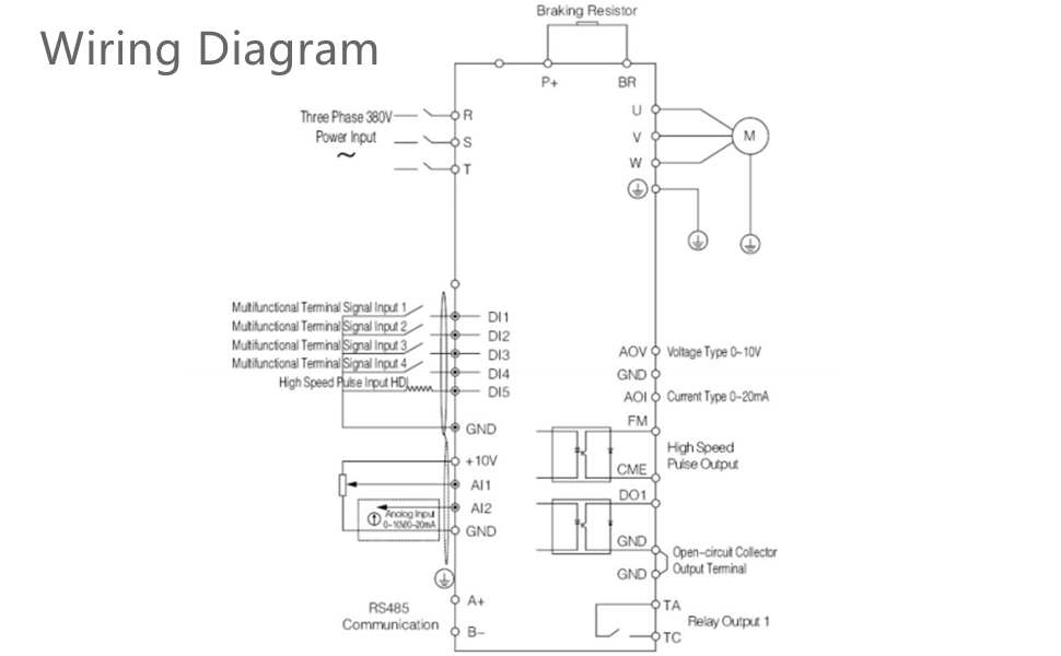
The wiring diagram illustrates the connections for the main power input, motor output, braking resistor, and various control signals. Ensure all connections are secure and comply with local electrical codes.
- Three Phase Power Input (R, S, T): Connect your 220V single-phase AC power to terminals R and T.
- Braking Resistor (P+, BR): Connect an external braking resistor if dynamic braking is required.
- Motor Output (U, V, W): Connect these terminals to your three-phase motor.
- Grounding: Always ensure proper grounding for safety.
- Control Terminals: The diagram shows connections for multifunctional digital inputs (DI1-DI5), analog inputs (AI1, AI2), analog output (AOV, AOI), high-speed pulse output (FM), open-circuit collector output (DO1), and RS485 communication (A+, B-).
6. Operating Instructions
The SKI780 offers flexible control options for various applications. Refer to the detailed programming manual (available as PDF) for specific parameter settings.
- V/F Control: Standard voltage/frequency control for general-purpose motor applications.
- Vector Control: Advanced control for improved torque response and speed regulation, especially at low speeds.
- Output Torque Control: Allows for precise control over the motor's output torque.
- Speed Control Modes: The unit supports 6 distinct speed control modes, configurable via the potentiometer or external panel.
- Integrated Communication: Utilize the built-in communication interface for remote control and monitoring.
- Synchronous and Proportional Timing Control: For applications requiring synchronized operations or precise timing.
- User-Defined Counter/Timer: Configure for specific counting or timing functions within your application.
- PID Regulation Function: Enables closed-loop control for maintaining constant temperature, pressure, or voltage.
- Keypad Lock: The unit allows for partial or full locking of the keypad to prevent unauthorized changes (analog potentiometer unlock function available).
- Digital Inputs/Outputs: Six opto-isolated digital inputs and two high-configuration outputs (normally open/closed relay) offer extensive control possibilities with 100 optional settings each.
- Analog Inputs/Outputs: Three analog inputs and one analog output channel provide flexible integration with external sensors and control systems.
7. Maintenance
Regular maintenance ensures the longevity and reliable operation of your SKI780 Frequency Converter.
- Cleaning: Keep the unit clean and free from dust and debris. Use a soft, dry cloth for cleaning. Do not use liquid cleaners.
- Ventilation: Ensure adequate airflow around the unit to maintain proper heat dissipation. Regularly check that ventilation openings are not obstructed.
- Connections: Periodically inspect all wiring connections for tightness and signs of wear or corrosion. Loose connections can lead to poor performance or damage.
- Environmental Conditions: Verify that the operating environment continues to meet the specified temperature and humidity requirements.
- Heat Sink: Ensure the heat sink remains clear of obstructions and dust buildup to prevent overheating.
8. Troubleshooting
This section provides general guidance for common issues. For detailed error codes and solutions, refer to the comprehensive PDF manual.
| Problem | Possible Cause | Solution |
|---|---|---|
| Motor does not start | Incorrect wiring, no power, emergency stop active, incorrect parameters. | Check power supply, verify wiring connections (R, T for single-phase input), ensure emergency stop is disengaged, review motor parameters. |
| Motor runs roughly or makes unusual noise | Motor parameters not tuned, motor mismatch, poor grounding. | Perform auto-tuning for the motor, ensure motor and VFD power ratings are compatible, check grounding. |
| Overheating | Insufficient ventilation, overloaded motor, high ambient temperature. | Ensure proper clearance around the unit, reduce motor load, improve ventilation in the operating area. |
| Display shows error code | Specific fault detected by the VFD. | Refer to the detailed PDF user manual for a list of error codes and their corresponding troubleshooting steps. |
9. Warranty and Support
For any questions or issues after purchase, please contact YWBL-WH customer support. We are committed to providing high-quality after-sales service and will address your inquiries seriously.
A detailed user manual in PDF format is available for download. This document contains comprehensive programming instructions and advanced troubleshooting guides.
PDF Manual: Download User Manual (PDF)
