
REOLINK Reolink Junction Box B10
REOLINK Junction Box B10 Instruction Manual
Model: Reolink Junction Box B10
Brand: REOLINK
1. Introduction
The REOLINK Junction Box B10 is designed to provide a clean, secure, and weatherproof solution for managing the wiring of compatible REOLINK bullet cameras. It allows for the concealment of Ethernet cables and RJ45 connectors, protecting them from environmental elements and potential vandalism. This manual provides detailed instructions for the proper installation and maintenance of your Junction Box B10.

Image: REOLINK Junction Box B10, showcasing its compact and robust design.
2. Key Features
- Durable Construction: Made of high-quality aluminum alloy for long-lasting performance.
- Weatherproof Design: Provides waterproof protection, suitable for both indoor and outdoor electrical and communication installations.
- Easy Installation: Designed for convenient and straightforward setup.
- Wire Management: Effectively stores and protects camera tail-cables and connectors, ensuring a tidy and professional appearance.

Image: Various angles of the REOLINK Junction Box B10, highlighting its robust construction and cable entry points.
3. Compatible REOLINK Cameras
The Junction Box B10 is specifically designed for a range of REOLINK bullet cameras. For optimal fit and functionality, refer to the compatibility list below. Note that some dome cameras may require the larger Junction Box D20.
3.1. Junction Box B10 Compatibility
This box is compatible with the following REOLINK camera models:
- PoE IP Cameras & NVRs: B500, B400, RLC-410-5MP, RLC-510A, RLC-510WA, B800, RLC-810A, RLC-811A, RLC-812A, RLC-1210A, RLC-1212A, B1200, RLC-81MA, RLC-81PA, CX410
- Wi-Fi Cameras & NVRs: RLC-511, RLC-511W, RLC-811A, RLC-811WA
- Dual-Lens Security Cameras: Reolink Duo WiFi, Reolink Duo PoE, Reolink Duo 2 PoE, Reolink Duo 2 WiFi
- Add-on Cameras: B400, B800
3.2. Junction Box D20 Compatibility (for reference)
While this manual focuses on the B10, the D20 is available for larger dome cameras and other models:
- PoE IP Cameras & NVRs: RLC-420, RLC-422, RLC-423, RLC-520, RLC-520A, RLC-522, RLC-820A, RLC-824A, RLC-822A, RLC-833A, RLC-842A, RLC-823A, E1 Outdoor PoE, RLC-1224A, RLC-1220A, RLC-823A 16X, RLC-843A, E1 Outdoor SE PoE
- Wi-Fi Cameras & NVRs: RLC-542WA, RLC-523WA, E1 Outdoor, E1 Outdoor Pro, E1 Outdoor CX, RLC-843WA
- Add-on Cameras: D400

Image: Visual representation of compatible REOLINK camera models for B10 and D20 junction boxes.
4. Package Contents
Upon opening your package, you should find the following items:
- REOLINK Junction Box B10 x1
- Mounting Screws and Wall Anchors
- Machine Screws for Camera Attachment
- Mounting Template
5. Installation Guide
Proper installation of the junction box is crucial for protecting your camera's wiring and ensuring a professional appearance. The junction box provides a secure enclosure for the camera's tail-cables, which often contain Ethernet and power connectors that are not easy to hide or protect when simply routed through a small hole.
5.1. General Considerations
- For installations where wiring can be routed directly into a ceiling or attic space (e.g., through a soffit), a 3/4-inch hole is typically required to accommodate the Ethernet connector.
- For installations on solid surfaces like concrete, brick, or siding where direct routing is not feasible, or where a smaller hole is preferred, the junction box is ideal. It allows for a smaller hole (just enough for the Ethernet or 12V wire) to be drilled, with the larger connectors and excess wiring neatly contained within the box.
5.2. Installation Steps for Bullet Cameras (e.g., RLC-810A)
Follow these steps for installing your bullet camera with the Junction Box B10:
- Prepare the Surface: Choose your desired mounting location. If routing cables through the wall, drill a small hole for the cable to pass through.
- Mount the Junction Box Base: Secure the base of the Junction Box B10 to the wall using the provided mounting screws and wall anchors. Ensure it is firmly attached.
- Route Cables: Feed the camera's tail-cables through one of the side access holes of the junction box. The box includes a waterproof gland for the main cable entry. For a secure, weatherproof seal, ensure the cable fits snugly within this gland and tighten it. Note that thinner Cat5e cables may not achieve as good a seal as thicker Cat6 cables.
- Connect Camera Wiring: Connect the Ethernet cable and any power cables from your camera to your network and power source.
- Tuck in Excess Wiring: Carefully tuck all excess wiring and connectors inside the junction box.
- Attach Camera to Cover: Align the camera's mounting base with the appropriate screw holes on the junction box cover (refer to the included template for specific hole patterns for your camera model). Secure the camera to the cover using the provided machine screws.
- Secure the Cover: Place the cover with the attached camera onto the junction box base. Ensure the rubber grommet for the central access hole (if used for cable pass-through from the camera) is properly seated for weather sealing. Secure the cover to the base using the remaining screws.

Image: Step-by-step visual guide for installing a REOLINK bullet camera with the Junction Box B10, showing cable routing and assembly.
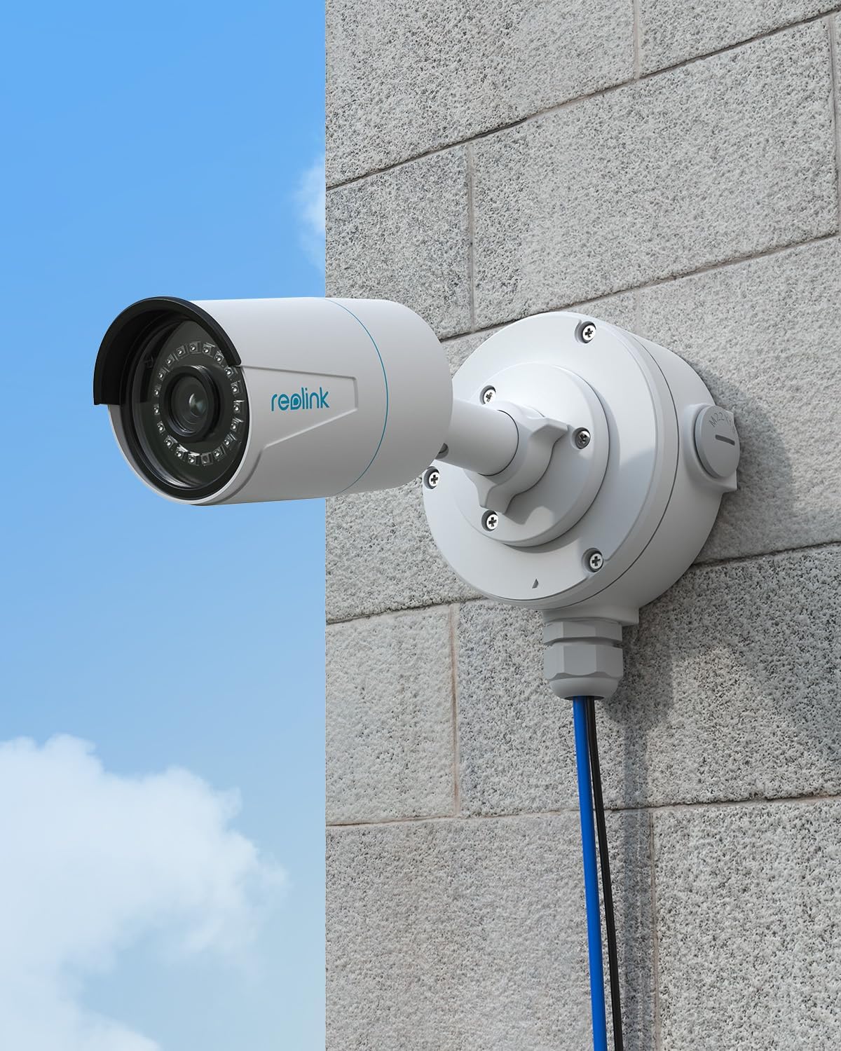
Image: A REOLINK bullet camera neatly installed on a wall using the Junction Box B10, demonstrating a clean and professional setup.
5.3. Installation Steps for Dome Cameras (e.g., E1 Outdoor PoE with D20)
While the B10 is primarily for bullet cameras, the larger D20 box follows a similar installation principle for dome cameras. This section is for reference if you are using a D20 box with a compatible dome camera:
- Prepare the Surface: As with bullet cameras, prepare the mounting surface and route necessary cables.
- Mount the Junction Box Base: Secure the D20 junction box base to the wall. The D20 also features multiple access holes for vertical or horizontal conduit installation.
- Route Cables: Feed the camera's tail-cables through the appropriate access hole and secure with the waterproof gland.
- Connect Camera Wiring: Connect the Ethernet and power cables.
- Tuck in Excess Wiring: Neatly tuck all excess wiring inside the D20 junction box.
- Attach Camera to Cover: For dome cameras like the E1 Outdoor PoE, align its plastic mount with the designated C-holes on the D20 cover. Secure the mount using machine screws.
- Secure the Cover: Place the cover with the attached camera onto the junction box base, ensuring the central rubber grommet is in place for weather sealing. Secure the cover to the base.
6. Specifications
| Attribute | Detail |
|---|---|
| Material | Aluminium Alloy |
| Dimensions (L x W x H) | 4.8 x 0.01 x 1.79 inches (122 x 112.5 x 45.5 mm) |
| Item Weight | 13.1 ounces |
| International Protection Rating | IP54 (Dust protected, Splash resistant) |
| Mounting Type | Wall Mount |
| Included Items | Junction box B10 x1 |

Image: Detailed dimensions of the REOLINK Junction Box B10.
7. Maintenance
To ensure the longevity and continued performance of your REOLINK Junction Box B10, consider the following maintenance tips:
- Regular Cleaning: Periodically wipe down the exterior of the junction box with a soft, damp cloth to remove dust and debris. Avoid abrasive cleaners.
- Inspect Seals: Annually inspect the rubber seals and glands for any signs of wear, cracking, or damage. Ensure they remain tightly sealed to maintain waterproofing.
- Check Fasteners: Verify that all mounting screws and camera attachment screws remain tight. Re-tighten if necessary to prevent movement or water ingress.
8. Troubleshooting
If you encounter issues with your REOLINK Junction Box B10, consider the following common troubleshooting steps:
- Water Inside Box: If you notice moisture or water inside the junction box, immediately disconnect power to the camera. Check all cable glands and the main cover seal for proper seating and damage. Ensure the cable used with the waterproof gland is of appropriate thickness to create a tight seal.
- Loose Camera: If the camera feels loose on the junction box, ensure all machine screws attaching the camera to the cover are securely tightened.
- Difficulty Closing Cover: If the cover does not close properly, ensure all excess wiring is neatly tucked inside the box and not obstructing the cover's path. Verify that no cables are pinched.
9. Warranty and Support
For detailed warranty information and technical support, please refer to the official REOLINK website or contact REOLINK customer service directly. Keep your purchase receipt for warranty claims.
Official REOLINK Website: https://reolink.com
Related documentsReolink Junction Box B10


Ask a question about this manual
Ask about setup, troubleshooting, compatibility, parts, safety, or missing instructions. Manuals+ will review the question and use this page’s manual context to help answer it.