
1. Introduction
The LAFVIN Mega 2560 R3 is a microcontroller board based on the ATmega2560-16AU. It is designed to be fully compatible with the Arduino IDE, offering an expanded set of features compared to standard boards. This manual provides essential information for setting up, operating, and maintaining your LAFVIN Mega 2560 R3 board.
Key features include:
- 100% compatibility with Arduino IDE.
- ATmega2560-16AU microcontroller for enhanced performance and memory.
- 256 KB of flash memory for program storage.
- 54 digital input/output pins, including 15 for PWM output.
- 16 analog input pins.
- 4 hardware serial ports (UARTs).
- Includes a USB cable for easy connectivity.
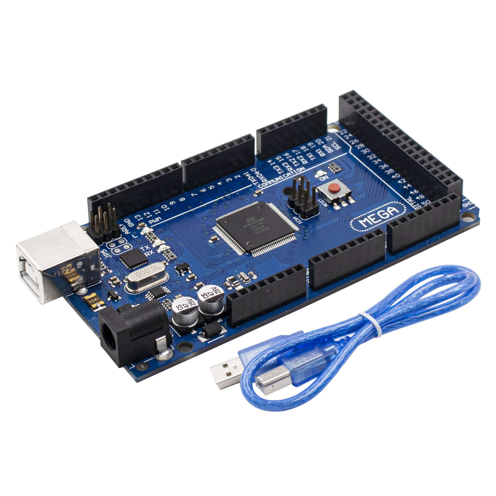
Figure 1: LAFVIN Mega 2560 R3 board and USB cable.
2. Product Overview and Components
The LAFVIN Mega 2560 R3 board features various components essential for its operation. Understanding these components is crucial for proper use and development.
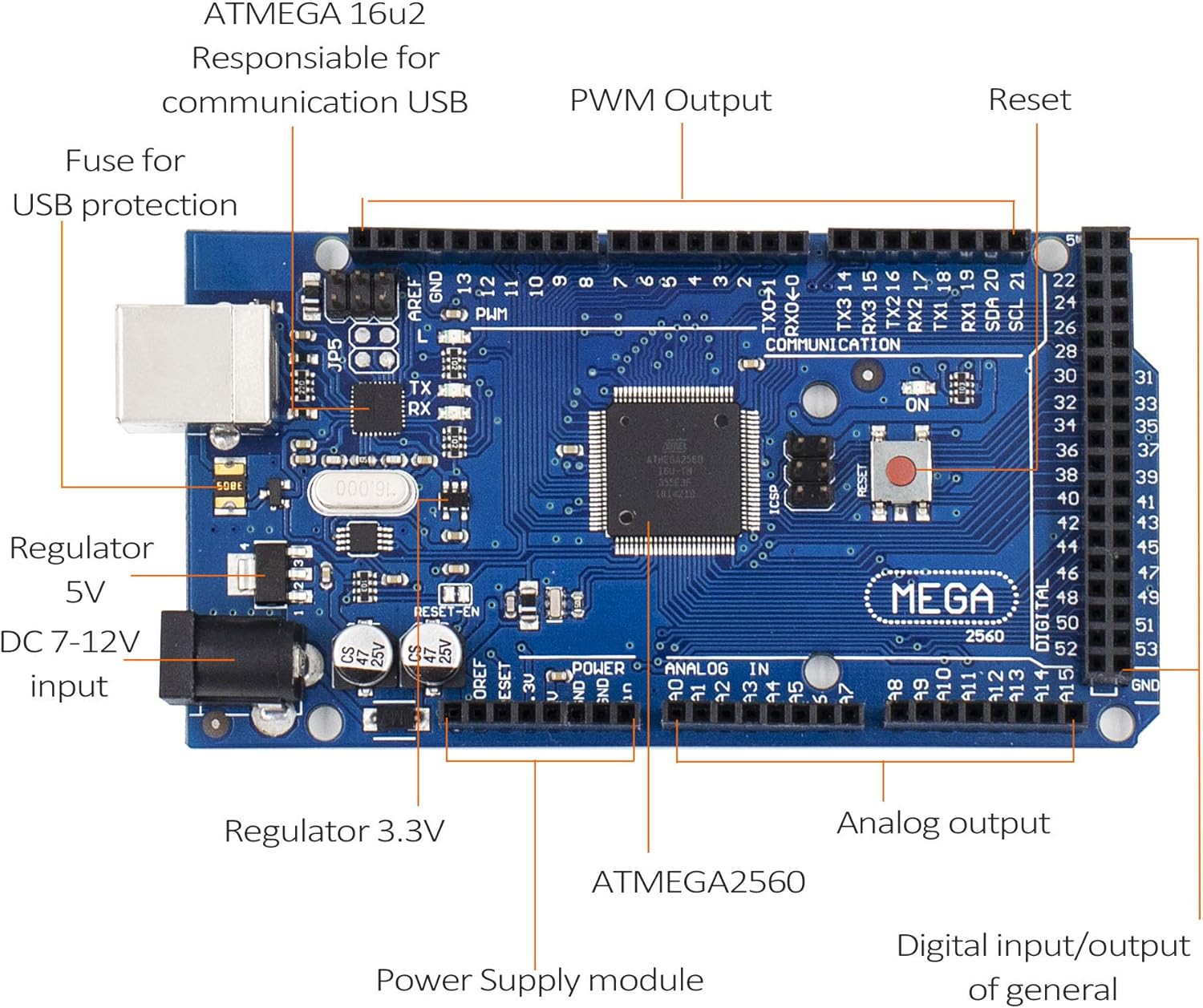
Figure 2: Key components of the LAFVIN Mega 2560 R3 board.
Key components include:
- ATmega2560 Microcontroller: The main processor of the board.
- ATMEGA 16U2: Responsible for USB communication.
- Digital I/O Pins (0-53): Used for digital input and output, with pins 2-13 and 44-46 supporting PWM.
- Analog Input Pins (A0-A15): Used for reading analog sensor data.
- USB Port: For connecting to a computer for programming and power.
- DC Power Jack (7-12V input): Alternative power input.
- Reset Button: Resets the microcontroller.
- Power LED (ON): Indicates the board is powered.
- TX/RX LEDs: Indicate data transmission and reception over USB.
- Voltage Regulators (5V, 3.3V): Provide stable power to the board and connected components.
- ICSP Header: For In-Circuit Serial Programming.
3. Specifications
The following table details the technical specifications of the LAFVIN Mega 2560 R3 board:
| Feature | Specification |
|---|---|
| Microcontroller | ATmega2560-16AU |
| Operating Voltage | 5V |
| Input Voltage (recommended) | 7-12V |
| Digital I/O Pins | 54 (15 provide PWM output) |
| Analog Input Pins | 16 |
| DC Current per I/O Pin | 20 mA |
| DC Current for 3.3V Pin | 50 mA |
| Flash Memory | 256 KB (8 KB used by bootloader) |
| SRAM | 8 KB |
| EEPROM | 4 KB |
| Clock Speed | 16 MHz |
| USB Ports | 1 |
| Model Number | LA-024 |
| UPC | 763231735768 |
4. Setup
To begin using your LAFVIN Mega 2560 R3 board, follow these simple setup steps:
- Connect to Computer: Use the provided USB cable to connect the LAFVIN Mega 2560 R3 board to your computer. The USB port on the board is located near the DC power jack.
- Install Arduino IDE: If you haven't already, download and install the Arduino IDE from the official Arduino website (www.arduino.cc/en/software).
- Select Board and Port: Open the Arduino IDE. Go to Tools > Board and select "Arduino Mega or Mega 2560". Then, go to Tools > Port and select the serial port corresponding to your connected board. This is typically labeled with "(Arduino Mega 2560)" or similar.
- Power Options: The board can be powered via the USB connection or an external power supply (7-12V DC) connected to the DC power jack. Ensure the power supply polarity is correct if using an external adapter.

Figure 3: LAFVIN Mega 2560 R3 board connected via USB.
5. Operating Instructions
Once the board is set up, you can begin programming and interacting with it using the Arduino IDE.
- Writing Code (Sketches): Use the Arduino IDE to write your programs (called sketches). The ATmega2560 microcontroller provides ample flash memory (256 KB) for complex projects.
- Uploading Sketches: After writing your code, click the "Upload" button in the Arduino IDE. The IDE will compile your sketch and upload it to the LAFVIN Mega 2560 R3 board. The TX/RX LEDs on the board will blink during the upload process.
- Using Digital I/O: The 54 digital pins can be configured as inputs or outputs using
pinMode(),digitalWrite(), anddigitalRead()functions. Pins marked with a tilde (~) support Pulse Width Modulation (PWM) for analog-like output. - Using Analog Inputs: The 16 analog input pins (A0-A15) can read varying voltage levels from sensors using the
analogRead()function. - Serial Communication: The board has four hardware serial ports (Serial, Serial1, Serial2, Serial3), allowing for communication with other devices or debugging via the Serial Monitor in the Arduino IDE.
6. Maintenance
Proper care and maintenance will ensure the longevity and reliable operation of your LAFVIN Mega 2560 R3 board.
- Handle with Care: Avoid touching the electronic components directly, especially when the board is powered, to prevent electrostatic discharge (ESD) damage.
- Storage: Store the board in an anti-static bag or a dry, non-conductive environment when not in use.
- Cleaning: If necessary, gently clean the board with a soft, dry brush or compressed air to remove dust. Do not use liquids or abrasive cleaners.
- Power Supply: Always use a stable power supply within the recommended voltage range (7-12V for external power). Over-voltage can damage the board.
- Avoid Short Circuits: Ensure that no conductive materials accidentally bridge pins or components, which could cause short circuits.
7. Troubleshooting
If you encounter issues with your LAFVIN Mega 2560 R3 board, consider the following troubleshooting steps:
- Board Not Detected:
- Ensure the USB cable is securely connected to both the board and your computer.
- Check if the power LED (ON) on the board is illuminated.
- Verify that the correct board type ("Arduino Mega or Mega 2560") and serial port are selected in the Arduino IDE.
- Try a different USB port or USB cable.
- Sketch Upload Errors:
- Confirm the correct board and port are selected.
- Ensure no other software is using the serial port.
- Check your code for syntax errors.
- Press the reset button on the board just before uploading.
- Unexpected Behavior:
- Review your code logic carefully.
- Check all wiring connections to external components.
- Ensure external power supplies are providing the correct voltage and current.
- Power Issues:
- If using an external power supply, ensure it is within the 7-12V range and provides sufficient current for your project.
- Avoid drawing excessive current from the 5V or 3.3V pins, as this can damage the onboard regulators.
8. Warranty and Support
For warranty information, technical support, or further assistance with your LAFVIN Mega 2560 R3 board, please refer to the official LAFVIN website or contact their customer service directly. Details are typically provided with your purchase documentation or on the product packaging.