
1. Introduction
This manual provides essential information for the safe and efficient operation of your Marsrock 1300W MPPT Pure Sine Wave Grid-Tie Micro Inverter. This device is designed to convert direct current (DC) from solar panels or wind turbines into alternating current (AC) for use in home solar and wind power systems, feeding excess power back into the utility grid. It features advanced Maximum Power Point Tracking (MPPT) technology for optimal energy harvesting and delivers a pure sine wave output suitable for sensitive electronics. Please read this manual thoroughly before installation and operation.
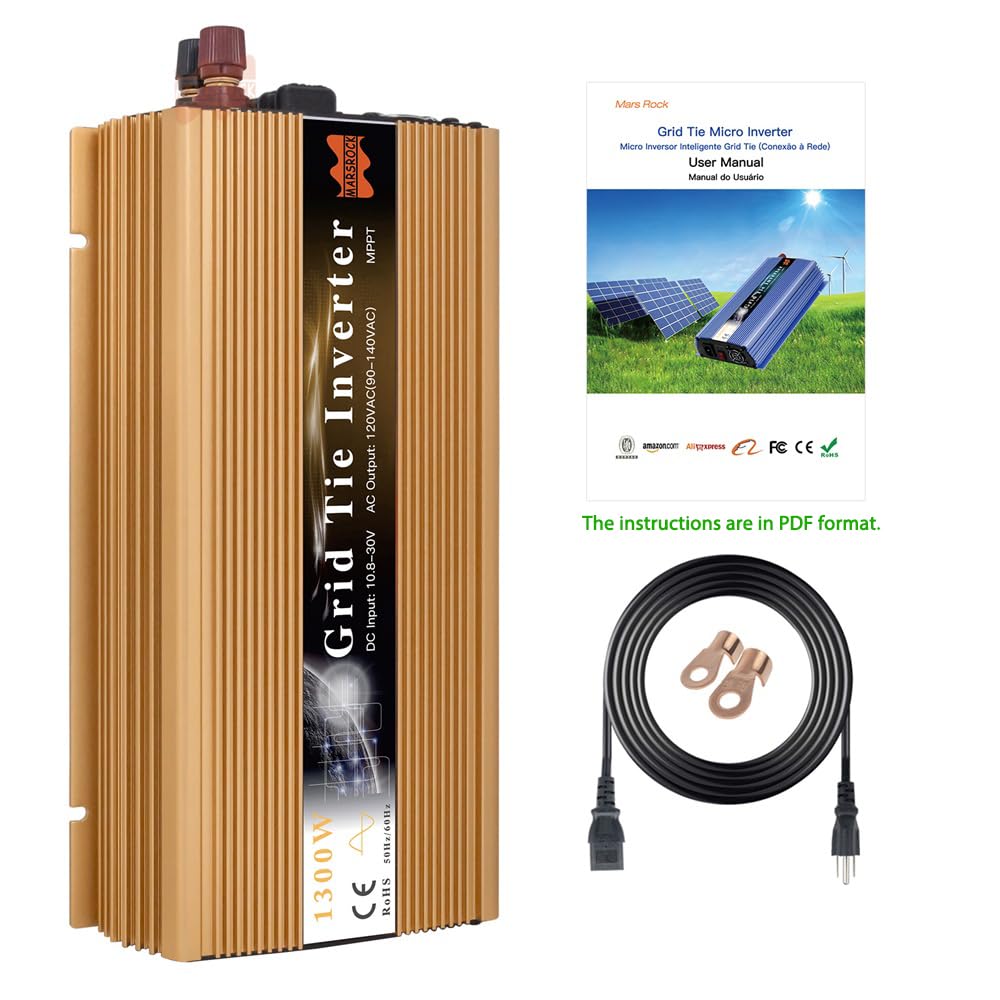
Figure 1: Marsrock 1300W Grid-Tie Micro Inverter
2. Safety Information
Always observe the following safety precautions to reduce the risk of electric shock, fire, or injury:
- Installation must be performed by qualified personnel in accordance with local electrical codes and regulations.
- Do not attempt to disassemble, repair, or modify the inverter. Refer all servicing to qualified service personnel.
- Ensure all DC and AC voltage sources are disconnected before performing any maintenance or wiring.
- Do not connect the battery after the utility grid is turned on.
- Ensure the input voltage and power of the solar panel do not exceed the range specified by the inverter.
- The inverter must be connected only to a dedicated branch circuit.
- Maximum branch circuit over current protection: 30A.

Figure 2: Important Safety Warning
3. What's in the Box
Upon opening the package, verify that all the following items are included:
- Inverter Body
- Install kits
- Instruction Manual

Figure 3: Package Contents (Inverter, cables, manual)
4. Product Overview
The Marsrock 1300W Grid-Tie Micro Inverter is housed in a durable aluminum alloy casing, designed for efficient heat dissipation. It features clearly labeled input and output terminals, status indicators, and a power switch.

Figure 4: Inverter Front and Back Panel Layout. This image shows the AC Grid connection, Power Switch, DC Indicator (Run/Error), Fan, DC Input (+/-), and Fuse ports.

Figure 5: AC Output Side. This view highlights the AC GRID port, Power Switch, and RUN/ERROR indicator lights.

Figure 6: DC Input Side. This view shows the DC Input terminals (+/-) and the replaceable fuses.

Figure 7: Integrated Cooling Fan. The inverter includes an intelligent built-in cooling fan to manage heat and ensure efficient operation.
5. Setup and Installation
Follow these steps for proper installation of your micro inverter:
5.1. Mounting the Inverter
Choose a cool, dry, and well-ventilated location for mounting the inverter. Ensure adequate clearance around the unit for proper airflow and heat dissipation. The inverter can be mounted vertically or horizontally.

Figure 8: Inverter Dimensions. The inverter measures approximately 280mm (11 inches) in length, 125mm (4.9 inches) in width, and 55mm (2.2 inches) in height.
5.2. DC Input Connection (Solar Panels/Wind Turbine)
Connect the DC output from your solar panels or wind turbine to the DC input terminals of the inverter. Ensure correct polarity (+ to + and - to -). The inverter accepts a DC input voltage range of 20-50V.
Video 1: Demonstrates the DC input connection process for the GTI1300 inverter. It shows connecting the positive and negative terminals from a DC power source (simulating solar panels) to the inverter's DC input ports.
5.3. AC Output Connection (Grid-Tie)
Connect the AC output cable from the inverter to a standard 110V/120V AC outlet in your home. This connection allows the inverter to feed power into your home's electrical system and, if generation exceeds consumption, back into the utility grid.
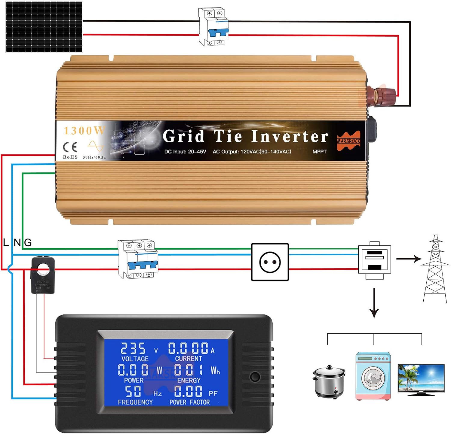
Figure 9: Typical Wiring Diagram. This diagram illustrates the connection of solar panels to the inverter, and the inverter's AC output to the home's electrical system and the utility grid, often through a bi-directional meter.
6. Operating Instructions
6.1. Powering On
- Ensure all DC input connections from your solar panels/wind turbine are secure.
- Connect the AC output cable from the inverter to a suitable AC outlet.
- Turn on the main power switch on the inverter. The red ERROR light will illuminate briefly, then the blue AC GRID light will turn on, and the green RUN light will begin flashing.
- The green RUN light will flash as the inverter synchronizes with the grid. Once synchronized and generating power, the green RUN light will remain steadily on.
Video 2: Illustrates the startup sequence of a 1300W Micro Inverter. It shows connecting DC input, turning on the power switch, and observing the indicator lights as the inverter connects to the AC grid and begins operation.
6.2. Indicator Lights
- RUN (Green LED): Flashing indicates grid synchronization in progress. Solid ON indicates normal operation and power generation.
- ERROR (Red LED): Indicates a fault or abnormal operating condition. Refer to the Troubleshooting section.
- AC GRID (Blue LED): Solid ON indicates a stable connection to the AC utility grid.
7. Maintenance
Regular maintenance ensures optimal performance and longevity of your inverter:
- Cleaning: Periodically clean the inverter's exterior, especially the cooling fins and fan vents, to prevent dust buildup and ensure efficient heat dissipation. Use a soft, dry cloth.
- Inspection: Regularly check all electrical connections for tightness and signs of corrosion or damage. Inspect cables for wear and tear.
- Environment: Ensure the installation environment remains within the specified temperature and humidity ranges.
8. Troubleshooting
If you encounter issues with your inverter, refer to the following common problems and solutions:
- Inverter not turning on / No lights: Check DC input connections and voltage from solar panels. Ensure the power switch is ON. Verify AC grid connection.
- Red ERROR light is on: This indicates a fault. Common causes include incorrect voltage/current, overheating, or grid instability. Disconnect both DC and AC power, wait a few minutes, then reconnect. If the error persists, contact support.
- Green RUN light flashing continuously: The inverter is attempting to synchronize with the grid. This can take a few minutes. If it flashes for an extended period (e.g., more than 5 minutes) or never goes solid, check AC grid stability and voltage.
- Low power output: Check solar panel cleanliness and shading. Verify DC input voltage and current are within optimal ranges. Ensure ambient temperature is not excessively high.
9. Specifications
| Feature | Value |
|---|---|
| Product Dimensions | 2.2 x 5 x 11 inches |
| Item Weight | 6.27 pounds |
| Item model number | GTI1300W36V110VG-GM |
| Brand | Marsrock |
| Recommended Uses For Product | Home |
| Power Source | Solar Powered |
| Wattage | 1300 watts |
| Model Name | GTI Series Inverter |
10. Warranty and Support
Marsrock offers an after-sales guarantee for its products. In the event of a product fault, the company will determine the cause and provide free replacement parts or replace the product as necessary. For technical assistance or warranty claims, please contact Marsrock technical support.
For more information and to explore other Marsrock products, visit the official Marsrock Store.