
1. Introduction
This manual provides detailed instructions for the installation, operation, and maintenance of the Vikye MC901 PID Temperature Controller. The MC901 is designed for precise temperature regulation in various industrial and scientific applications, featuring high sensitivity and accurate control capabilities.
2. Safety Information
- Always disconnect power before installation or maintenance to prevent electric shock.
- Ensure proper wiring according to the provided diagrams to avoid damage to the unit or connected equipment.
- Do not operate the controller in environments with excessive moisture, dust, or corrosive gases.
- Verify that the power supply voltage matches the controller's specifications (85-265V AC, 50/60Hz).
- Only qualified personnel should perform installation and troubleshooting.
3. Product Overview
The Vikye MC901 is a digital PID temperature controller featuring a compact design and versatile output options. It supports K-type and PT100 thermocouple inputs and offers both relay and SSR outputs.
3.1 Key Features
- Built-in high precision chip for high sensitivity and accurate temperature control.
- Supports ℃/℉ temperature display.
- Digital display resolution of 0.1 ℃/0.1℉ when thermocouple is input.
- Integrated Relay and SSR output options.
- Short shell design (85mm depth) for easy mounting.
3.2 Front Panel Layout

Figure 1: Front view of the MC901 controller showing PV (Process Value) and SV (Set Value) displays, along with OUT, AT, ALM1, ALM2 indicators, and control buttons (SET, R/S, Up, Down).

Figure 2: The digital display of the MC901, illustrating the 0.1 ℃/℉ resolution for thermocouple inputs.
3.3 Dimensions and Mounting

Figure 3: Physical dimensions of the MC901 controller, showing a width of 96mm (3.8in), height of 96mm (3.8in), and a depth of 85mm (3.3in).

Figure 4: The MC901 controller shown with its included mounting brackets for panel installation.
3.4 Rear Panel and Wiring Terminals
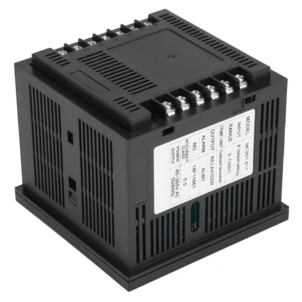
Figure 5: Rear view of the MC901 controller, displaying the various wiring terminals for power, sensor input, and control outputs.
4. Setup and Installation
4.1 Panel Mounting
- Cut a panel opening of 92x92mm (3.62x3.62 inches).
- Insert the MC901 controller into the opening from the front.
- Secure the controller using the provided mounting brackets from the rear of the panel.
4.2 Wiring
Refer to the wiring diagram typically found on the side label of the unit or in the full product documentation. Ensure all connections are secure and correctly polarized.

Figure 6: Side label of the MC901, detailing model information, input type (K default), temperature range, output type (Relay/SSR), power supply, and accuracy class. This label also contains critical wiring information.
- Power Supply: Connect 85-265V AC, 50/60Hz to the designated power terminals.
- Sensor Input: Connect your K-type thermocouple or PT100 sensor to the input terminals. Observe polarity for thermocouples.
- Output: Connect your heating/cooling element or SSR to the appropriate output terminals (Relay or SSR).
- Alarm Outputs: If utilizing, connect alarm devices to ALM1 and ALM2 terminals.
5. Operating Instructions
5.1 Power On
Once wired correctly, apply power to the controller. The PV (Process Value) display will show the current temperature, and the SV (Set Value) display will show the setpoint.
5.2 Setting the Temperature (SV)
- Press the SET button once. The SV display will begin to flash.
- Use the Up and Down arrow buttons to adjust the desired temperature setpoint.
- Press SET again to confirm the new setpoint and exit the setting mode.
5.3 Parameter Settings
To access advanced parameters (e.g., input type, control mode, alarm settings), press and hold the SET button for several seconds until the parameter code appears on the PV display. Use the Up and Down buttons to navigate through parameters and the SET button to enter and save changes for each parameter. Consult the full product manual for a complete list of parameters and their functions.
5.4 Auto-Tuning (AT)
The MC901 features an auto-tuning function to optimize PID parameters for your specific system. To initiate auto-tuning:
- Set your desired temperature setpoint (SV).
- Press and hold the AT button (often combined with R/S) until the AT indicator light illuminates.
- The controller will cycle the output to determine optimal PID values. This process may take some time.
- Once auto-tuning is complete, the AT indicator will turn off, and the controller will operate with the newly calculated PID parameters.
6. Maintenance
- Keep the controller clean and free from dust. Use a soft, dry cloth for cleaning.
- Regularly check wiring connections for tightness and signs of wear or corrosion.
- Ensure adequate ventilation around the unit to prevent overheating.
- Avoid exposing the controller to direct sunlight or extreme temperatures.
7. Troubleshooting
| Problem | Possible Cause | Solution |
|---|---|---|
| No display/Power off | No power supply; Incorrect wiring; Blown fuse | Check power connections; Verify wiring; Replace fuse if applicable. |
| PV display shows 'HHHH' or 'LLLL' | Sensor open circuit; Sensor short circuit; Sensor out of range; Incorrect sensor type setting | Check sensor wiring; Replace faulty sensor; Ensure sensor range matches application; Verify input type setting in parameters. |
| Temperature not stable/Overshoot | PID parameters not optimized; External disturbances | Perform auto-tuning; Manually adjust PID parameters; Check for external factors affecting temperature. |
| Output not activating | Wiring error; Output type setting incorrect; Faulty output component | Verify output wiring; Check output type (Relay/SSR) in parameters; Test output component. |
| Cannot change ℉ to ℃ (or vice versa) | Temperature unit parameter not set correctly | Access parameter settings and change the temperature unit (e.g., 'C-F' parameter). |
8. Specifications
| Feature | Specification |
|---|---|
| Model | MC901 |
| Input Type | K-type Thermocouple (default), PT100 |
| Temperature Range | 0-1300 ℃ (for K-type) |
| Temperature Unit | Celsius (℃), Fahrenheit (℉) |
| Output Type | Relay / SSR (integrated) |
| Accuracy Class | 0.5 |
| Power Supply | 85-265V AC, 50/60Hz |
| Display Type | Digital |
| Product Dimensions | 4.33 x 4.33 x 3.94 inches (110 x 110 x 100 mm) |
| Weight | 8.47 ounces (240 grams) |
9. Warranty and Support
This product typically comes with a standard manufacturer's warranty. Please refer to your purchase documentation or contact your retailer for specific warranty terms and conditions. For technical support or further assistance, please contact Vikye customer service through their official channels or the vendor from whom you purchased the product.