
1. Overview
The Envistia XL4015 DC-DC Step-Down Buck Converter is a versatile power module designed for efficient voltage conversion. It features Constant Voltage (CV) and Constant Current (CC) control, making it suitable for various applications such as driving LEDs, charging lithium batteries, or serving as a laboratory power source. The integrated digital meter provides real-time display of input voltage, output voltage, output current, and output power, eliminating the need for external measurement tools.
2. Package Contents
Please verify that all items are present and in good condition upon opening the package:
- 1x XL4015 DC-DC Step-Down Buck Converter Module with Digital Meter
- 4x Mounting Standoffs and Nuts
3. Safety Information
- Always ensure correct polarity when connecting input and output wires. Incorrect connections can damage the module and connected devices.
- Do not exceed the maximum input voltage (36VDC) or output current (5A peak, 4A continuous) specified for the module.
- Ensure adequate ventilation, especially when operating at higher currents, to prevent overheating.
- Avoid short-circuiting the output terminals. The module has built-in short protection, but prolonged short circuits can cause damage.
- Keep the module away from moisture, dust, and extreme temperatures.
- This product is intended for experienced users familiar with electronics and power supply circuits.
4. Product Features
- PWM buck (step-down) DC/DC voltage converter module.
- Constant Voltage (CV) and Constant Current (CC) control.
- High efficiency up to 96%.
- Integrated digital meter displays input/output voltage, output current, and output power.
- Adjustable output voltage (1.2V to 34V) and current (0A to 5A peak).
- Built-in thermal shutdown, current limit, and output short protection.
- Screw terminal input connections and screw terminals or USB connector for output.
5. Setup
5.1 Component Identification
Familiarize yourself with the components of the XL4015 module:
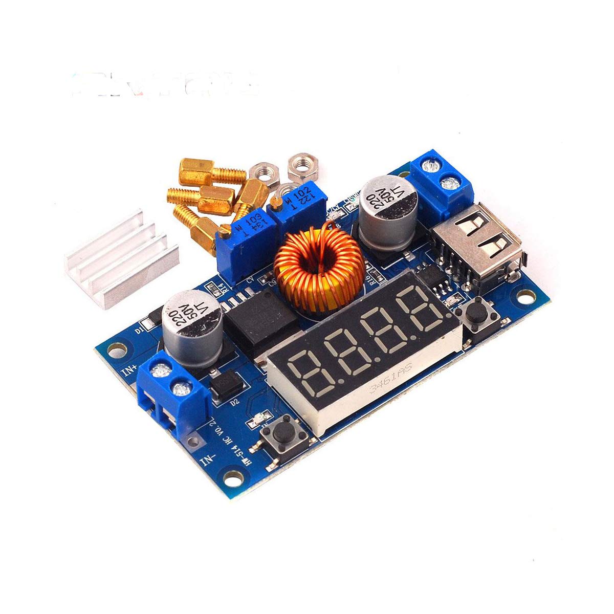
Figure 1: XL4015 Module with included mounting hardware.

Figure 2: Top view of the XL4015 module.

Figure 3: Bottom view and dimensions of the XL4015 module.
5.2 Wiring Connections
Connect your power source and load to the module using the screw terminals:
- Input: Connect your DC power source (5V-36VDC) to the IN+ (positive) and IN- (negative) terminals.
- Output: Connect your load to the OUT+ (positive) and OUT- (negative) terminals. The USB port can also be used for output.
Video 1: This video demonstrates the basic connections and operation of an XL4015 DC-DC Buck Step-Down Voltage Power Module Converter, showing how to connect input and output and adjust settings.
5.3 Initial Power-Up and Adjustment
Before connecting your final load, it is recommended to set the desired output voltage and current:
- Connect the input power source. The digital display will light up.
- Use a multimeter to measure the output voltage.
- Adjust the Voltage Potentiometer (usually the one closer to the output terminals) clockwise to increase voltage, counter-clockwise to decrease. Set to your desired output voltage.
- To set the current limit (Constant Current mode):
- Short-circuit the output terminals (e.g., with an ammeter or a thick wire for a brief moment).
- Adjust the Current Potentiometer (usually the one closer to the input terminals) to set the maximum desired output current.
- Remove the short circuit.
- Connect your load. The module will now regulate the output according to your settings.
Video 2: This video provides a preview and operational guide for a similar power module, demonstrating how to adjust voltage and current settings.
6. Operating Instructions
6.1 Digital Display Functions
The digital display cycles through various parameters. Use the onboard buttons to switch between display modes:
- Short Press Button 1 (left): Cycles through Output Voltage (V), Output Current (A), Output Power (W).
- Short Press Button 2 (right): Cycles through Input Voltage (V), Output Voltage (V).
- Long Press Button 1 (left): Toggles the USB output ON/OFF.
Video 3: This video illustrates the display functions and adjustment process for a variable voltage regulator, which is similar in operation to the XL4015 module.
6.2 Constant Voltage (CV) Mode
In CV mode, the module maintains a constant output voltage as set by the voltage potentiometer, provided the input voltage is sufficient and the load current does not exceed the set current limit.
6.3 Constant Current (CC) Mode
In CC mode, the module maintains a constant output current as set by the current potentiometer, typically used for charging batteries or driving LEDs. The output voltage will adjust to maintain the set current.
7. Maintenance
- Keep the module clean and free from dust and debris. Use a soft, dry cloth for cleaning.
- Regularly check all connections to ensure they are secure.
- Ensure the module is operated within its specified temperature range.
- No user-serviceable parts inside. Do not attempt to disassemble or repair the module.
8. Troubleshooting
- No Display/No Output: Check input power connections and ensure the input voltage is within the 5V-36VDC range. Verify polarity.
- Output Voltage Too Low/High: Adjust the voltage potentiometer. Ensure the input voltage is at least 2V greater than the desired output voltage.
- Output Current Not Reaching Desired Level: Check the current potentiometer setting. Ensure the load is not drawing more current than the module can supply or is set to.
- Module Overheating: Reduce the load current or ensure adequate ventilation. Operating at maximum current for extended periods may require additional cooling.
9. Specifications
| Feature | Value |
|---|---|
| Input Voltage Range | 5V - 36VDC |
| Output Voltage Range | 1.2V - 34VDC (adjustable) |
| Output Current | 0A - 5A peak, 4A continuous |
| Output Power | 75W maximum |
| Voltmeter Range | 1.2V to 40.0V, 0.1V resolution |
| Current Meter Range | 0.00A to 5.00A, 0.01A resolution |
| Power Meter Range | 0.0W to 99.9W, 0.1W resolution |
| Operating Frequency | 180KHz |
| Efficiency | Up to 96% |
| Protection Features | Thermal shutdown, current limit, output short protection |
| Dimensions (LxWxH) | 6.6 x 3.9 x 1.8 cm (2.6 x 1.5 x 0.7 inches, including standoffs) |
10. Warranty and Support
For warranty information and technical support, please refer to the seller's policies or contact Envistia Mall directly through your purchase platform. Keep your purchase receipt for any warranty claims.


