
1. Introduction
This manual provides detailed instructions for the WINGONEER 1.44-inch TFT LCD Module, which features a 128x128 pixel resolution and is controlled by the ST7735 chip via an SPI serial interface. This module is designed for integration with various microcontrollers, including 51 series and ARM-based systems, offering a compact and colorful display solution for your projects.
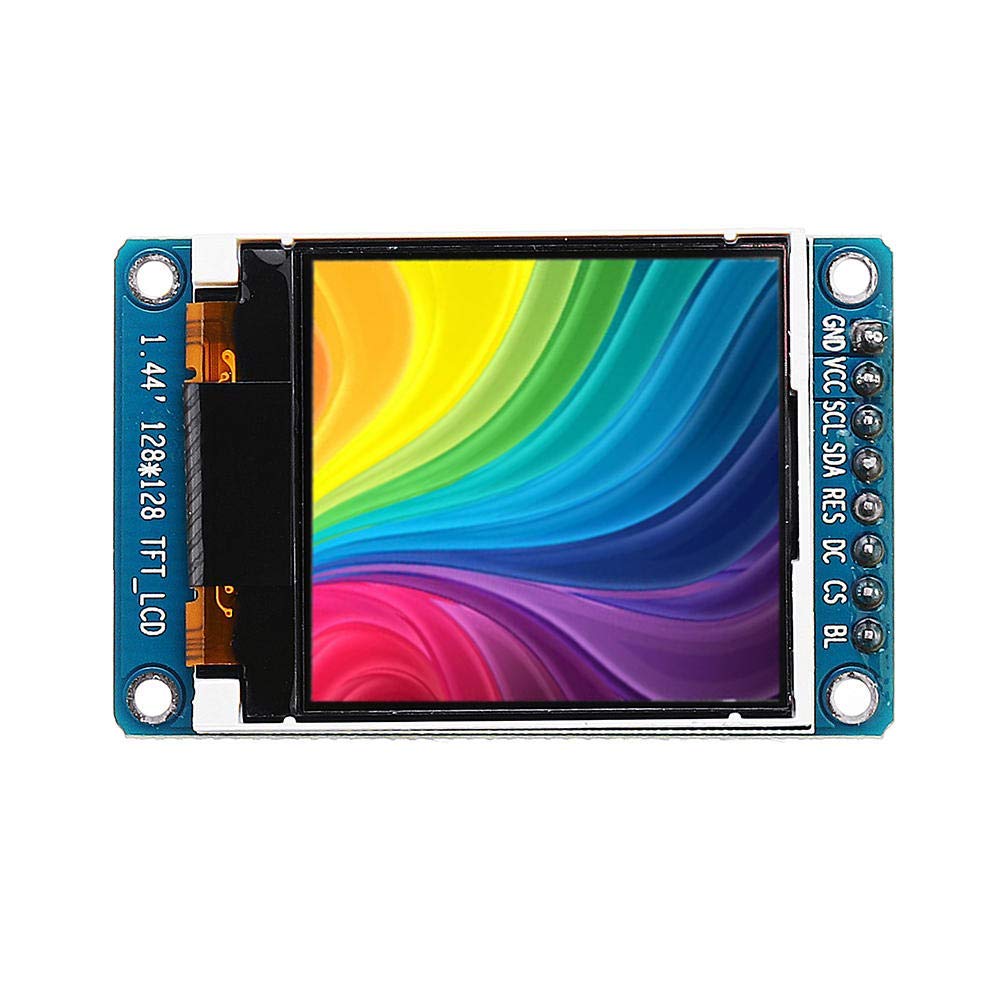
Image 1.1: Angled view of the WINGONEER 1.44-inch TFT LCD Module, highlighting its compact design and pin connections.
2. Product Features
- Display Size: 1.44 inches
- Display Material: TFT LCD
- Resolution: 128 x 128 pixels
- Control Chip: ST7735
- Interface Type: SPI Serial Interface
- Number of Pins: 8-PIN
- Working Voltage: 2.8V - 3.3V
- Working Temperature: -20℃ to 70℃
3. Package Contents
The product package includes the following item:
- 1 x WINGONEER 1.44-inch TFT Display Module
4. Setup and Pin Definitions
Before connecting the module, familiarize yourself with the pin definitions to ensure correct wiring with your microcontroller. Incorrect connections can damage the module or your development board.
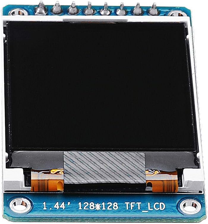
Image 4.1: Front view of the WINGONEER 1.44-inch TFT LCD Module, clearly showing the 8-pin header and their labels.
4.1. Interface Pin Definitions
| Pin No. | Label | Description |
|---|---|---|
| 1 | GND | Power Ground |
| 2 | VCC | Power Input (2.8V - 3.3V) |
| 3 | SCL | SPI Clock Input |
| 4 | SDA | SPI Data Input |
| 5 | RES | Reset Pin |
| 6 | DC | Data/Command Select Pin |
| 7 | CS | Chip Select Signal (Low level active) |
| 8 | BLK | Backlight Control (Low level turns off backlight; can be left floating for default operation) |
4.2. General Connection Guidelines
Connect the module to your microcontroller using the SPI interface. Ensure that the VCC and GND pins are connected to the appropriate power supply (2.8V-3.3V). The SCL, SDA, RES, DC, and CS pins should be connected to digital I/O pins on your microcontroller. Refer to your microcontroller's documentation for specific SPI pin assignments.
5. Operating the Module
To operate the 1.44-inch TFT LCD module, you will typically need to use a software library compatible with the ST7735 controller. Many microcontrollers, such as Arduino and ESP32/ESP8266, have existing libraries that simplify the process of initializing the display and drawing graphics or text.
5.1. Initialization
The initialization sequence for the ST7735 controller involves sending a series of commands to set up the display's internal registers, including power control, gamma correction, and frame rate. Most libraries handle this automatically.
5.2. Displaying Graphics and Text
Once initialized, you can use library functions to draw pixels, lines, rectangles, circles, and display text. The 128x128 resolution allows for basic graphical interfaces and data visualization. Remember that the module operates at 3.3V logic levels; ensure your microcontroller's I/O pins are compatible or use level shifters if necessary.
6. Specifications
| Feature | Detail |
|---|---|
| Display Size | 1.44 inches |
| Display Material | TFT LCD |
| Resolution | 128 x 128 pixels |
| Control Chip | ST7735 |
| Display Area | 25.5 x 26.5 mm |
| Module Size | 30.0 x 46.5 mm |
| Interface Type | SPI Interface |
| Number of Pins | 8-PIN |
| Working Voltage | 2.8V - 3.3V |
| Working Temperature | -20℃ to 70℃ |
| Battery Usage | No |
| Manufacturer | WINGONEER |
| ASIN | B07QC62SJX |
| Date First Available | April 3, 2019 |

Image 6.1: Back view of the WINGONEER 1.44-inch TFT LCD Module, showing the PCB layout and components.
7. Maintenance
To ensure the longevity and optimal performance of your TFT LCD module, follow these maintenance guidelines:
- Handling: Always handle the module by its edges to avoid touching the display surface or electronic components.
- Cleaning: Use a soft, lint-free cloth, slightly dampened with water or a specialized screen cleaner, to gently wipe the display surface. Avoid abrasive materials or harsh chemicals.
- Storage: Store the module in a dry, dust-free environment, away from direct sunlight and extreme temperatures.
- Power Supply: Ensure the power supply voltage is within the specified range (2.8V-3.3V) to prevent damage.
- Static Electricity: Take precautions against electrostatic discharge (ESD) when handling the module, as electronic components are sensitive to static.
8. Troubleshooting
If you encounter issues with your WINGONEER 1.44-inch TFT LCD Module, consider the following troubleshooting steps:
- No Display/Blank Screen:
- Verify all power connections (VCC, GND) are correct and within the specified voltage range.
- Check all SPI data and control line connections (SCL, SDA, RES, DC, CS) for proper wiring.
- Ensure the backlight control pin (BLK) is correctly configured or left floating if not actively controlled.
- Confirm that the display initialization code in your software is running correctly.
- Garbled or Incorrect Display:
- Check for correct SPI mode and clock polarity/phase settings in your software.
- Verify that the data sent to the display matches the expected format (e.g., color depth, byte order).
- Ensure the display orientation settings (if applicable in your library) are correct.
- Module Not Responding:
- Confirm that the reset pin (RES) is being toggled correctly during initialization.
- Check for any short circuits or damaged pins on the module or connecting wires.
9. Warranty and Support
Specific warranty information for this product is not provided in the available data. For any technical support or warranty inquiries, please refer to the retailer or manufacturer's official website where the product was purchased. Always retain your proof of purchase for any warranty claims.