
1. Introduction
The EPEVER TRIRON 1206N is a modular Maximum Power Point Tracking (MPPT) solar charge controller designed for efficient and reliable power management in off-grid solar systems. This controller automatically detects 12V or 24V DC system voltages and features a modular design for flexible configuration. It ensures optimal charging of various battery types, including Sealed, Gel, Flooded, LiFePO4, and Li-NiCoMn, while protecting against common electrical faults.
2. Key Features
- Modular design with optional LCD and LED displays for varied requirements.
- Supports hot-swapping functionality for certain modules.
- Real-time power statistics recording function.
- Comprehensive protection functions: PV over current, PV short circuit, Lithium battery low temperature, night reverse charging, battery reverse polarity, PV reverse polarity, battery over discharge, battery over heat, battery over voltage, load short circuit, load overload, and controller overheating.
- Peak conversion efficiency of 98% and tracking efficiency of ≥99.5%.
- Automatic system voltage identification and wide MPP operating voltage range.
- Multiple load work modes: manual control, light ON/OFF, light ON + timer.
3. Safety Instructions
Please read all instructions and warnings in this manual before installation and operation.
- Electrical Safety: Always disconnect power from the solar array and battery before installing or adjusting the controller. Use appropriate circuit breakers or fuses for all connections.
- Battery Handling: Batteries can produce explosive gases. Ensure adequate ventilation. Wear eye protection and gloves when working with batteries. Do not short-circuit battery terminals.
- Installation Environment: Install the controller in a well-ventilated area, away from direct sunlight, high temperatures, and moisture. Ensure sufficient clearance around the controller for heat dissipation.
- Wiring: Use correctly sized cables for all connections to prevent overheating and ensure efficient power transfer. Ensure all connections are tight and secure.
- Qualified Personnel: Installation and maintenance should be performed by qualified personnel familiar with solar power systems and electrical safety procedures.
- Grounding: The controller features negative ground. Ensure proper grounding according to local electrical codes.
4. Product Overview
The TRIRON 1206N controller is designed with a modular structure, allowing for customization and easy maintenance.

Figure 4.1: EPEVER TRIRON 1206N Solar Charge Controller showing overall dimensions (135mm x 177mm x 48mm).
The controller's modular design allows for different display and interface modules to be integrated.

Figure 4.2: Exploded view showing the modular components of the TRIRON 1206N, including the main unit, display module, and interface module.
The rear of the controller features a heat sink for efficient thermal management.
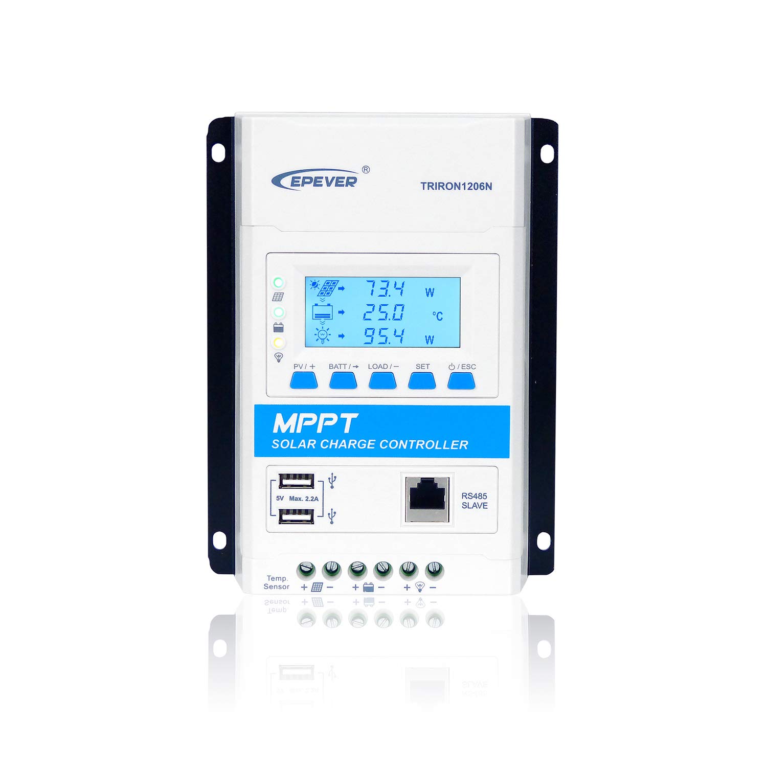
Figure 4.3: Rear view of the TRIRON 1206N, highlighting the integrated heat sink fins for cooling.
The product label provides essential model and specification details.

Figure 4.4: Product label displaying model number (TRIRON1206N), type (DS2/UCS), voltage (12/24V), current (10A), max PV voltage (60V), and max PV input power (130W/12V, 260W/24V).
5. Setup and Installation
Follow these steps for safe and correct installation of your TRIRON 1206N solar charge controller.
- Mounting: Choose a suitable location for mounting the controller. It should be indoors, protected from direct sunlight, high temperatures, and water. Ensure good ventilation. Mount the controller vertically on a wall or panel using the provided mounting holes.
- Wiring Sequence: Connect the components in the following order to prevent damage:
- Step 1: Connect the Battery: Connect the battery to the controller's battery terminals (BATT+/-). Ensure correct polarity. The controller will detect the system voltage.
- Step 2: Connect the Load: Connect the DC load to the controller's load terminals (LOAD+/-). Ensure correct polarity.
- Step 3: Connect the Solar Panel: Connect the solar panel array to the controller's PV terminals (PV+/-). Ensure correct polarity.
WARNING: Always connect the battery first, then the load, and finally the solar panel. Disconnect in the reverse order: solar panel, then load, then battery. Incorrect wiring sequence can damage the controller and other components.
- Temperature Sensor (RT-S): Connect the optional remote temperature sensor to the designated port. This improves battery charging accuracy by compensating for temperature variations.
- Communication Ports: If using external communication modules (e.g., MT50, eBox-WIFI-01), connect them to the RS485 SLAVE port. The controller also features dual USB ports (5V, 2.2A max) for charging small devices.

Figure 5.1: Wiring diagram for the TRIRON 1206N, showing connections for solar panel, battery, DC load, remote temperature sensor, and communication accessories (MT50, eBox-WIFI-01, PC/Laptop, Smartphone).
6. Operating Instructions
Once installed, the TRIRON 1206N operates automatically. The optional display module provides real-time system status and allows for parameter adjustments.
6.1. Display and Buttons
The display module (if installed) shows various parameters such as PV voltage, battery voltage, charging current, load current, and system status. Buttons are typically used for navigating menus and adjusting settings. Refer to the specific display module manual for detailed operation.

Figure 6.1: Front view of the TRIRON 1206N with the LCD display module showing system parameters.
6.2. Battery Type Setting
The controller supports various battery types. It is crucial to set the correct battery type for optimal charging and battery longevity.
- Supported types include: Sealed, Gel, Flooded, LiFePO4, Li-NiCoMn, and User-defined Lithium battery.
- Consult the display module manual or communication software for instructions on how to select and configure the battery type.
6.3. Load Work Modes
The controller offers multiple load control modes:
- Manual Control: The load can be turned ON/OFF manually via the controller's buttons or communication software.
- Light ON/OFF: The load automatically turns ON at dusk and OFF at dawn.
- Light ON + Timer: The load turns ON at dusk and stays ON for a set duration (e.g., 2 hours, 4 hours).
These modes can be configured through the display module or external communication tools.
7. Maintenance
Regular maintenance ensures the longevity and optimal performance of your solar charge controller.
- Check Connections: Periodically inspect all wiring connections for tightness and corrosion. Loose connections can cause voltage drops and overheating.
- Clean Controller: Keep the controller clean and free from dust and debris. Ensure the heat sink fins are not obstructed to allow for proper cooling. Use a dry cloth for cleaning.
- Battery Inspection: Regularly check battery terminals for corrosion and ensure battery fluid levels (for flooded batteries) are adequate.
- System Performance: Monitor the system's performance through the display or monitoring software. Note any unusual readings or behavior.
- Environmental Check: Ensure the installation environment remains within the recommended temperature and humidity ranges.
8. Troubleshooting
This section provides guidance for common issues. For more complex problems, contact EPEVER technical support.
| Problem | Possible Cause | Solution |
|---|---|---|
| No display/Controller not powering on | Battery not connected or low voltage; reversed battery polarity; loose connections. | Check battery connections and voltage. Ensure correct polarity. Tighten all terminals. |
| No charging from solar panel | PV array disconnected; reversed PV polarity; PV voltage too low/high; shading on panels. | Check PV connections and polarity. Ensure PV voltage is within controller's operating range. Clear any shading. |
| Load not working | Load disconnected; reversed load polarity; load overcurrent; battery low voltage disconnect. | Check load connections and polarity. Reduce load. Allow battery to charge. Check load mode settings. |
| Controller overheating | Poor ventilation; excessive ambient temperature; overloaded system. | Ensure adequate airflow around the controller. Relocate to a cooler area if necessary. Reduce system load. |
9. Specifications
Technical specifications for the EPEVER TRIRON 1206N Solar Charge Controller.
| Parameter | Value |
|---|---|
| Model | TRIRON 1206N (DS2/UCS) |
| Nominal System Voltage | 12V/24VDC Auto Work |
| Rated Charge Current | 10A |
| Rated Discharge Current | 10A |
| Battery Input Voltage Range | 8V ~ 32V |
| Max. PV Open Circuit Voltage | 60V (at min operating environment temp); 46V (at 25℃ environment temp) |
| MPP Voltage Range | (Vbat + 2V) ~ 36V |
| Max. PV Input Power | 130W/12V; 260W/24V |
| Battery Type | Sealed / Gel / Flooded; LiFePO4 / Li-NiCoMn / User Lithium battery |
| Product Dimensions | 135 x 180.8 x 47.3 mm |
| Net Weight | 0.56 kg |
| Manufacturer | EPEVER |
| ASIN | B07N2RN28C |
| UPC | 791280364974 |
10. Warranty and Support
EPEVER products are manufactured to high-quality standards. For warranty information, please refer to the warranty card included with your product or visit the official EPEVER website.
For technical support, troubleshooting assistance, or inquiries regarding your TRIRON 1206N controller, please contact EPEVER customer service.
- Manufacturer: EPEVER
- Support: Please refer to the contact information provided in your product packaging or on the official EPEVER website for the most up-to-date support channels.


