
1. Introduction
This manual provides essential information for the safe and effective use of the Aexit XW5-11N2 SPDT Control Microswitch. It covers product features, specifications, installation, operation, and maintenance. Please read this manual thoroughly before installation and operation, and retain it for future reference.

Figure 1.1: Aexit XW5-11N2 SPDT Control Microswitch with short hinge lever actuator.
2. Safety Information
Observe the following safety precautions to prevent injury or damage to the product. This device operates with electrical current and requires careful handling.
- Electrical Hazard: Ensure power is disconnected before installation, wiring, or maintenance to prevent electric shock.
- Professional Installation: Installation and wiring should be performed by qualified personnel in accordance with local electrical codes and regulations.
- Avoid Casual Contact: Do not allow children or unauthorized personnel to have casual contact with the switch or its wiring.
- Handle with Care: Do not shake, drop, or apply excessive force to the switch. Mechanical stress can damage internal components.
- Environmental Conditions: Avoid using the switch in extreme temperatures, near open flames, or in environments with super high temperatures. Ensure the operating environment is within specified limits.
- Proper Wiring: Connect wires securely to the designated terminals. Loose connections can lead to overheating or malfunction.
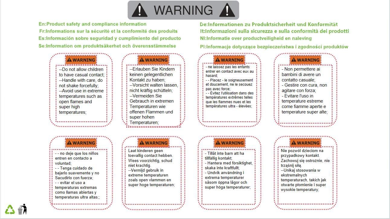
Figure 2.1: General safety warnings regarding handling, temperature, and contact.
3. Product Overview
The Aexit XW5-11N2 is a Single Pole Double Throw (SPDT) control microswitch featuring a short hinge lever actuator. It is designed for industrial control applications where precise monitoring of mechanical travel limits is required. The switch offers a high precision mechanism for acute operation and extended service life.
Key Features:
- Actuator Type: Short Hinge Lever
- Contact Configuration: 1 Normally Open (NO) and 1 Normally Closed (NC) (SPDT)
- Terminals: 3 Screw Terminals for secure wiring
- Action: Momentary
- Application: Industrial control, limit sensing
4. Specifications
Detailed technical specifications for the XW5-11N2 microswitch are provided below:
| Parameter | Value |
|---|---|
| Product Name | Limit Switch |
| Model | XW5-11N2 |
| Rated Voltage (Ue) | AC 380V, DC 220V |
| Rated Current (Ith) | 3A |
| Power Rating (Pe) | 100VA, 10W |
| External Material | Resin, Metal |
| Color | Black, Silver Tone |
| Contact Configuration | 1NO, 1NC (SPDT) |
| Actuator Action | Momentary |
| Actuator Type | Short Hinge Lever |
| Terminals | 3 Screw Terminals |
| Two Fixing Hole Distance | 2.5 cm / 1 inch |
| Fixing Hole Diameter | 0.4 cm / 0.16 inch |
| Lever Total Length | 4 cm / 1.5 inches |
| Switch Size (L*W*H) | 4.9 x 1.8 x 3 cm / 1.9 x 0.7 x 1.2 inches |
| Weight | 32g |
| Operation Mode | ON-NONE-OFF |
5. Setup and Installation
Proper installation is crucial for the reliable operation of the microswitch. Follow these steps carefully:
5.1 Mounting the Switch
- Power Disconnection: Ensure all power to the circuit is turned off before beginning installation.
- Select Location: Choose a mounting location that allows the actuator lever to be properly engaged by the moving part it is intended to sense. Ensure sufficient clearance for the lever's full range of motion.
- Secure Mounting: Use appropriate screws (not included) to secure the switch through its two fixing holes. The fixing hole distance is 2.5 cm (1 inch) and the diameter is 0.4 cm (0.16 inch). Ensure the switch is firmly mounted to prevent movement during operation.
5.2 Wiring Connections
The XW5-11N2 microswitch has three screw terminals for wiring:
- Common (C): This is the common terminal.
- Normally Open (NO): This terminal is open when the actuator is not pressed and closes when the actuator is pressed.
- Normally Closed (NC): This terminal is closed when the actuator is not pressed and opens when the actuator is pressed.
- Identify Terminals: Refer to the markings on the switch body to correctly identify the Common, NO, and NC terminals.
- Connect Wires: Strip the insulation from your wires to an appropriate length. Insert the wires into the corresponding screw terminals and tighten the screws securely. Ensure no loose strands of wire are present that could cause a short circuit.
- Verify Connections: Double-check all wiring connections for correctness and security before restoring power.
6. Operating Instructions
The Aexit XW5-11N2 microswitch operates as a momentary contact switch, typically used as a limit switch in automated systems.
- Actuation: The switch is actuated when the short hinge lever is pressed or moved by a mechanical force.
- Contact Change: Upon actuation, the Normally Open (NO) contact closes, and the Normally Closed (NC) contact opens.
- Release: When the mechanical force is removed from the lever, the actuator returns to its original position, and the contacts revert to their default states (NO opens, NC closes).
- Application: This functionality allows the switch to detect the presence, position, or travel limits of moving parts in machinery, triggering specific actions or signals within a control system.
7. Maintenance
The XW5-11N2 microswitch is designed for long-term reliability with minimal maintenance. However, periodic checks can help ensure optimal performance.
- Power Disconnection: Always disconnect power before performing any maintenance.
- Visual Inspection: Regularly inspect the switch for any signs of physical damage, wear on the actuator lever, or corrosion on the terminals.
- Cleanliness: Keep the switch free from dust, dirt, and debris, which can interfere with the actuator's movement or contact operation. Use a soft, dry cloth for cleaning.
- Wiring Integrity: Periodically check that all screw terminals are tight and that wires are securely connected.
- Actuator Function: Manually actuate the lever a few times (with power off) to ensure smooth movement and proper return.
8. Troubleshooting
If the microswitch is not functioning as expected, consider the following common issues and solutions:
- Switch Not Actuating:
- Check if the mechanical part is properly engaging the actuator lever. Adjust its position if necessary.
- Ensure the lever is not obstructed by debris or other components.
- No Electrical Response:
- Verify that power is supplied to the circuit.
- Inspect all wiring connections for looseness or incorrect wiring. Tighten terminals if needed.
- Check for continuity across the contacts (NO and NC) with a multimeter when the switch is actuated and released. If contacts do not change state, the switch may be faulty.
- Intermittent Operation:
- Loose wiring connections can cause intermittent contact. Re-tighten all terminals.
- Excessive vibration in the mounting area might affect consistent actuation. Ensure secure mounting.
- Contamination inside the switch mechanism could lead to inconsistent contact. If suspected, replacement may be necessary.
If troubleshooting steps do not resolve the issue, consider replacing the switch.
9. Warranty and Support
Specific warranty information for the Aexit XW5-11N2 microswitch may vary depending on the point of purchase. Please refer to your purchase documentation or contact your retailer for details regarding warranty coverage and support.
For technical inquiries or further assistance, please contact the manufacturer or your supplier.