
1. Introduction
This manual provides essential information for the safe and effective installation, operation, and maintenance of the Danfoss RT-121 Safety Air Pressure Switch. The RT-121 is designed for monitoring air pressure in various industrial applications, including air conditioning systems, boilers, and well pumps, ensuring system safety and optimal performance. Please read this manual thoroughly before proceeding with any installation or operation.
2. Safety Information
WARNING: Improper installation, operation, or maintenance can result in serious injury, death, or equipment damage. Only qualified personnel should install, operate, or service this device.
- Always disconnect power before installing or servicing the switch.
- Ensure the pressure system is depressurized before connecting or disconnecting the switch.
- Verify that the pressure range of the switch is suitable for the application.
- Adhere to all local and national electrical and safety codes.
- Protect the switch from physical damage and environmental extremes beyond its specified operating conditions.
3. Product Overview
The Danfoss RT-121 is a robust pressure switch designed for reliable performance in demanding environments. It features an adjustable pressure range and differential, allowing for precise control and monitoring of air pressure.
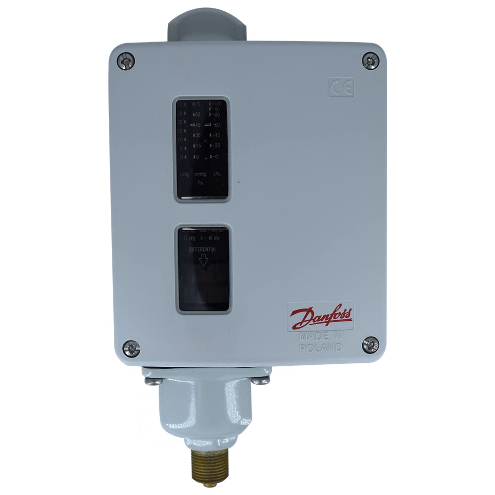
Figure 3.1: Front view of the Danfoss RT-121 pressure switch. This image displays the main grey housing, the visible adjustment windows for pressure settings, and the 'Danfoss Made in Poland' branding. The pressure connection is visible at the bottom.
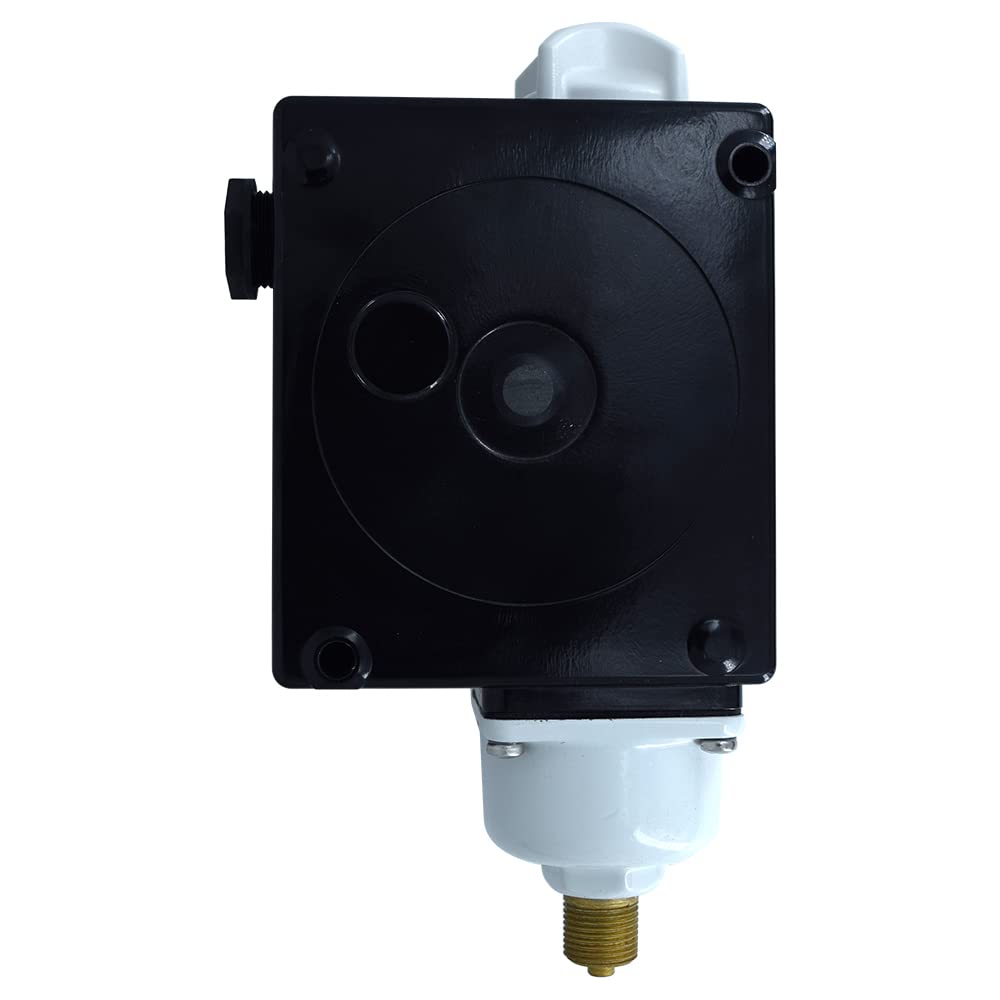
Figure 3.2: Rear view of the Danfoss RT-121 pressure switch. This image shows the black electrical connection box on the back of the unit, with screw points for mounting.

Figure 3.3: Front and side view of the Danfoss RT-121 pressure switch. This perspective illustrates the overall dimensions and the robust construction of the device.

Figure 3.4: Internal view of the Danfoss RT-121 pressure switch. The cover is removed, revealing the electrical terminals, the pressure sensing element, and the adjustment dials for setting the pressure range and differential.

Figure 3.5: Danfoss RT-121 pressure switch with included accessories. This image shows the pressure switch next to an assortment of washers, O-rings, and screws, which are typically used for installation and sealing.

Figure 3.6: Detailed view of the pressure connection. This close-up highlights the 3/8 inch threaded connection point at the base of the pressure switch, where it interfaces with the pressure system.

Figure 3.7: Application examples for the Danfoss RT-121. This image illustrates the versatility of the pressure switch, showing its use in diverse industrial settings such as steam boiler plants, diesel plants, power stations, and compressor systems.
4. Setup and Installation
Installation should only be performed by qualified technicians familiar with pressure systems and electrical wiring. Ensure all safety precautions are followed.
- Mounting: Securely mount the pressure switch in a location free from excessive vibration, direct sunlight, and extreme temperatures. Use appropriate fasteners for the mounting surface.
- Pressure Connection: Connect the switch to the pressure line using the 3/8 inch threaded connection. Ensure a leak-tight seal using appropriate sealant or tape. Do not overtighten.
- Electrical Wiring: Disconnect all power before wiring. Open the electrical enclosure. Connect the power supply and control circuit wires to the appropriate screw terminals (SPDT configuration). Refer to the wiring diagram provided inside the switch cover for correct connections. Ensure proper grounding.
- Pressure Setting: Adjust the main pressure setting and differential using the internal adjustment screws or dials. Refer to the 'Operating Instructions' section for details on setting the desired pressure range and differential.
- Verification: After installation, slowly pressurize the system and verify the switch operates at the desired set points. Check for any leaks in the pressure connection.
5. Operating Instructions
The Danfoss RT-121 pressure switch operates automatically based on the set pressure points. The primary adjustments are the main pressure set point and the differential.
- Setting the Main Pressure: The main pressure set point determines the pressure at which the switch will actuate (either open or close a circuit). This is typically adjusted via a main spring or dial. Consult the markings inside the switch for specific adjustment procedures and corresponding pressure values.
- Setting the Differential: The differential (or hysteresis) is the difference between the cut-in and cut-out pressure. This prevents rapid cycling of the connected equipment. Adjust the differential according to system requirements. A smaller differential means the switch reacts to smaller pressure changes, while a larger differential provides more stability.
- Monitoring: Once set, the switch will continuously monitor the system pressure. When the pressure reaches the set point, the internal contacts will change state (Normally Open to Closed, or Normally Closed to Open), triggering the connected control circuit.
6. Maintenance
The Danfoss RT-121 pressure switch is designed for minimal maintenance. Regular inspections are recommended to ensure continued reliable operation.
- Visual Inspection: Periodically inspect the switch for any signs of physical damage, corrosion, or loose connections.
- Pressure Connection: Check the pressure connection for leaks. Tighten if necessary, but do not overtighten.
- Electrical Connections: Ensure all electrical connections are secure and free from corrosion.
- Functionality Test: Periodically test the switch's operation by manually adjusting the system pressure to verify that the switch actuates at the set points.
- Cleaning: Keep the exterior of the switch clean and free from dust and debris. Do not use harsh chemicals.
7. Troubleshooting
If the pressure switch is not functioning as expected, consider the following common issues and solutions:
| Problem | Possible Cause | Solution |
|---|---|---|
| Switch does not actuate at set pressure. | Incorrect pressure setting; Clogged pressure port; Faulty wiring; Internal mechanical failure. | Verify pressure settings; Clean pressure port; Check wiring connections; Replace switch if internal failure is suspected. |
| Switch cycles too frequently. | Differential set too low; System pressure fluctuations. | Increase differential setting; Investigate and stabilize system pressure. |
| Leak at pressure connection. | Improper sealing; Damaged threads. | Re-apply sealant/tape and tighten connection; Replace connection if threads are damaged. |
| No electrical continuity. | Loose wiring; Corroded terminals; Internal contact failure. | Check and tighten all wiring; Clean terminals; Replace switch. |
If troubleshooting steps do not resolve the issue, contact Danfoss technical support or a qualified service technician.
8. Specifications
| Feature | Detail |
|---|---|
| Model Number | RT-121 |
| Brand | Danfoss |
| Pressure Range | -1 to 0 Bar |
| Operation Mode | Automatic |
| Contact Type | Normally Open (SPDT) |
| Connector Type | Screw Terminals |
| Terminal | SPDT |
| Circuit Type | 1-way |
| Contact Material | Copper |
| International Protection Rating | IP66 |
| Number of Positions | 2 |
| Control Method | Touch (for adjustment) |
| Item Weight | 2.2 Pounds |
9. Warranty and Support
Danfoss products are manufactured to high-quality standards and are typically covered by a manufacturer's warranty against defects in materials and workmanship. For specific warranty terms and conditions, please refer to the documentation included with your purchase or visit the official Danfoss website.
For technical assistance, troubleshooting beyond this manual, or to inquire about replacement parts, please contact Danfoss customer support. Contact information can usually be found on the Danfoss official website or through your local distributor.
Online Resources: For additional information, product updates, and detailed technical specifications, please visit the official Danfoss Store on Amazon or the main Danfoss corporate website.


