1. Introduction
The ASUS PRIME H310M-A R2.0/CSM is a Micro-ATX motherboard designed to support 8th and 9th generation Intel Core processors. It offers a robust platform for building a reliable and efficient desktop system, featuring ASUS 5X Protection III for hardware safeguards and FanXpert for advanced cooling control. This manual provides essential information for the proper installation, operation, and maintenance of your motherboard.

Figure 1.1: The ASUS PRIME H310M-A R2.0/CSM Motherboard alongside its retail packaging.
Key Features:
- Designed for 8th and 9th generation Intel Core processors (LGA 1151 socket).
- ASUS 5X Protection III for hardware-level safeguards and component longevity.
- FanXpert for dynamic system cooling control.
- Integrated M.2 slot with Intel Optane Memory compatibility for fast storage.
- ASUS Optic-MEM technology for improved memory stability and performance.
- On-board 8-channel HD audio for immersive sound.
- SafeSlot Core fortified PCIe slot for enhanced durability.
2. Package Contents
Before proceeding with the installation, please verify that all items listed below are present in your motherboard package. If any item is missing or damaged, contact your retailer.
- ASUS PRIME H310M-A R2.0/CSM motherboard
- Serial ATA 6.0Gb/s cables (2)
- I/O Shield
- Support DVD
- M.2 Anchor
- User's manual (this document)

Figure 2.1: All components included in the ASUS PRIME H310M-A R2.0/CSM motherboard package.
3. Motherboard Layout and Components
Familiarize yourself with the various components and connectors on your motherboard before installation.

Figure 3.1: Top-down view of the motherboard, highlighting key component locations such as the CPU socket, DIMM slots, and PCIe slots.

Figure 3.2: Angled view showcasing the CPU socket, RAM slots, and various headers.
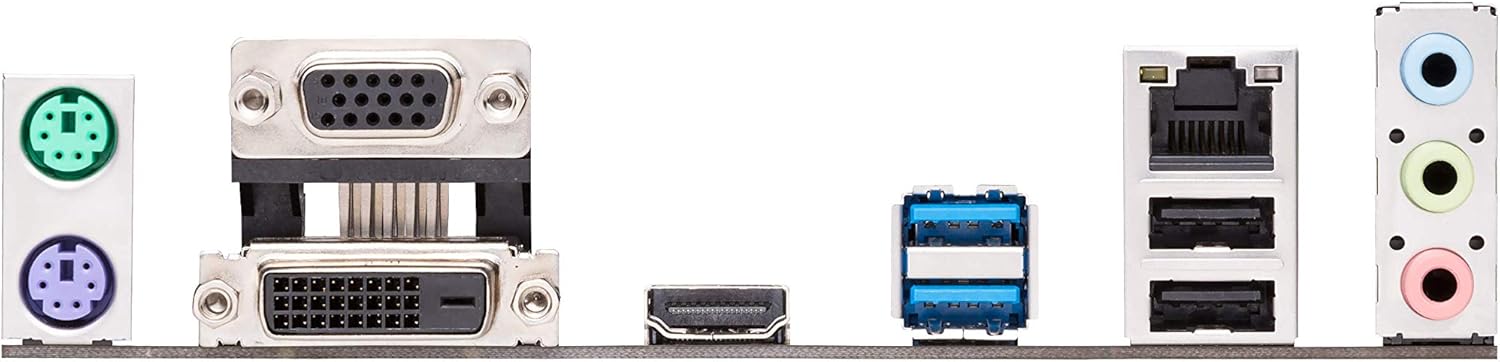
Figure 3.3: The rear input/output (I/O) panel, showing ports for USB, audio, video (VGA, DVI-D, HDMI), Ethernet, and PS/2.
Key Connectors:
- LGA 1151 CPU Socket: For Intel 8th/9th Gen Core, Pentium Gold, and Celeron processors.
- DDR4 DIMM Slots: Two slots supporting up to 32GB of DDR4 memory (2666/2400/2133 MHz).
- PCIe 3.0 x16 Slot: For graphics cards.
- PCIe 2.0 x1 Slots: Two slots for expansion cards.
- M.2 Socket 3: Supports M.2 SSDs (SATA & PCIe x2 mode).
- SATA 6Gb/s Ports: Four ports for SATA devices.
- USB 3.1 Gen 1 Ports: Rear panel and internal header.
- USB 2.0 Ports: Rear panel and internal headers.
- Front Panel Headers: For power button, reset button, HDD LED, and front panel audio.
- ATX Power Connectors: 24-pin EATX Power and 8-pin EATX 12V Power.
4. Setup and Installation
Follow these steps carefully to install your motherboard and its components.
4.1. Preparing Your System
- Static Electricity Precautions: Always wear an anti-static wrist strap or frequently touch a grounded metal object (like your computer case) to discharge static electricity before handling components.
- Workspace: Ensure you have a clean, well-lit, and spacious workspace.
- Power Off: Disconnect the power cord from the wall outlet before installing or removing any components.
4.2. CPU Installation
- Locate the LGA 1151 CPU socket on the motherboard.
- Push the load lever down and away from the socket to open the load plate.
- Carefully align the triangular mark on the CPU with the mark on the socket. Gently place the CPU into the socket. Do not force it.
- Close the load plate and push the load lever back into place until it clicks.
- Install the CPU cooler according to its manufacturer's instructions.
4.3. Memory (RAM) Installation
- Open the clips at both ends of the DIMM slots.
- Align the notch on the DDR4 memory module with the key in the DIMM slot.
- Insert the memory module firmly into the slot until the clips snap into place. Ensure both clips are closed.
4.4. M.2 SSD Installation
- Locate the M.2 slot on the motherboard.
- Remove the M.2 anchor screw from the standoff.
- Insert the M.2 SSD into the slot at a 30-degree angle.
- Gently push the SSD down and secure it with the M.2 anchor screw.
4.5. Motherboard Installation into Chassis
- Install the I/O shield into the chassis's rear I/O opening.
- Align the motherboard with the standoffs in your chassis.
- Secure the motherboard with screws. Do not overtighten.
4.6. Connecting Power Supply
- Connect the 24-pin ATX power cable from your power supply to the 24-pin EATX Power connector on the motherboard.
- Connect the 8-pin ATX 12V power cable to the 8-pin EATX 12V Power connector.
4.7. Connecting Peripherals and Front Panel
- Connect SATA data cables from your storage drives to the SATA 6Gb/s ports on the motherboard.
- Connect your graphics card to the PCIe 3.0 x16 slot (if applicable) and secure it.
- Connect front panel cables (Power SW, Reset SW, HDD LED, Power LED) to the corresponding headers on the motherboard. Refer to the motherboard diagram for exact pinouts.
- Connect USB and audio cables from your chassis front panel to the respective headers.
5. Operating Your System
5.1. Initial Boot-Up
After all components are installed and connected, connect your monitor, keyboard, and mouse. Plug in the power cord and press the power button on your chassis.
5.2. Accessing BIOS/UEFI
To enter the BIOS/UEFI setup utility, press the DEL key or F2 key during the Power-On Self-Test (POST) process. The BIOS allows you to configure system settings, boot order, and monitor hardware status.
5.3. Driver Installation
After installing your operating system, install the necessary drivers for your motherboard's components. You can find these drivers on the included Support DVD or download the latest versions from the official ASUS support website. Installing the correct drivers ensures optimal performance and stability.
5.4. Operating System Installation
Insert your operating system installation media (USB drive or DVD) and configure the boot order in the BIOS/UEFI to boot from it. Follow the on-screen instructions to install your preferred operating system.
6. Maintenance
6.1. Cleaning
Regularly clean your computer's interior to prevent dust buildup, which can lead to overheating and component failure. Use compressed air to remove dust from fans, heatsinks, and other components. Ensure the system is powered off and unplugged before cleaning.
6.2. BIOS Updates
ASUS periodically releases BIOS updates to improve system stability, add support for new hardware, or fix bugs. You can download the latest BIOS from the ASUS support website. Refer to the motherboard's product page or the BIOS utility for instructions on how to update the BIOS safely. It is recommended to update the BIOS before installing Windows, especially if using a 9th generation Intel CPU.
6.3. Driver Updates
Keep your drivers updated to ensure optimal performance and compatibility. You can check the ASUS support website for the latest chipset, audio, LAN, and other drivers for your motherboard.
7. Troubleshooting
This section provides solutions to common issues you might encounter.
- No Power/No Boot:
- Ensure all power cables (24-pin ATX, 8-pin 12V CPU) are securely connected to the motherboard and power supply.
- Verify the power supply is switched on and connected to a working power outlet.
- Check front panel power switch connections to the motherboard.
- No Display:
- Ensure your monitor is connected to the correct video output (either motherboard's integrated graphics ports or discrete graphics card).
- Reseat the graphics card and memory modules.
- If using a discrete graphics card, ensure it has adequate power from the PSU.
- System Instability/Crashes:
- Check CPU and GPU temperatures. Ensure cooling solutions are properly installed.
- Run memory diagnostic tools to check for faulty RAM.
- Ensure all drivers are up-to-date.
- Verify power supply wattage is sufficient for all components.
- Peripheral Not Detected:
- Try connecting the peripheral to a different port.
- Install or update relevant drivers.
- Check BIOS settings to ensure the port is enabled.
For more detailed troubleshooting or issues not covered here, please refer to the ASUS support website or contact technical support.
8. Specifications
Below are the technical specifications for the ASUS PRIME H310M-A R2.0/CSM Motherboard.
| Feature | Specification |
|---|---|
| Brand | ASUS |
| Model Name | PRIME H310M-A R2.0/CSM |
| CPU Socket | LGA 1151 |
| Compatible Processors | 8th and 9th Generation Intel Core, Pentium Gold, Celeron |
| Chipset Type | Intel H310 |
| RAM Memory Technology | DDR4 |
| Memory Slots | 2 x DIMM, Max. 32GB, DDR4 2666/2400/2133 MHz Non-ECC, Un-buffered Memory |
| Memory Clock Speed | 2666 MHz |
| Graphics Output | VGA, DVI-D, HDMI |
| Expansion Slots | 1 x PCIe 3.0/2.0 x16, 2 x PCIe 2.0 x1 |
| Storage | 1 x M.2 Socket 3, 4 x SATA 6Gb/s port(s) |
| USB Ports | USB 3.1 Gen 1 (Type-A), USB 2.0/1.1 |
| Audio | Realtek ALC887 8-Channel High Definition Audio CODEC |
| LAN | Realtek RTL8111H Gigabit LAN Controller |
| Form Factor | mATX (8.9 inch x 7.3 inch) |
| Product Dimensions | 8.9 x 1 x 7.3 inches |
| Item Weight | 1.2 pounds |
| Date First Available | December 12, 2018 |
9. Warranty and Support
9.1. Product Warranty
This ASUS motherboard comes with a limited warranty. The duration and terms of the warranty may vary by region and retailer. Please retain your proof of purchase for warranty claims. For detailed warranty information, refer to the warranty card included in your package or visit the official ASUS website.
9.2. Technical Support
For technical assistance, driver downloads, BIOS updates, or further information regarding your ASUS PRIME H310M-A R2.0/CSM motherboard, please visit the official ASUS support website:
You may also find helpful resources, FAQs, and contact information for regional support centers on the website.


