
1. Product Overview
The Aexit CJX2-2510 AC Contactor is an electrical device designed for long-distance connection and disconnection of circuits, as well as frequent starting and control of AC electric motors. It features a 3-pole, normally open (NO) contact type, making it suitable for various industrial control applications.
This contactor is engineered for reliability and efficiency, offering low power consumption, a lightweight design, and a long service life. It is compatible with international quality standards including IEC 60947.4, NFC 63110, VDE0660, and GB14048.4.
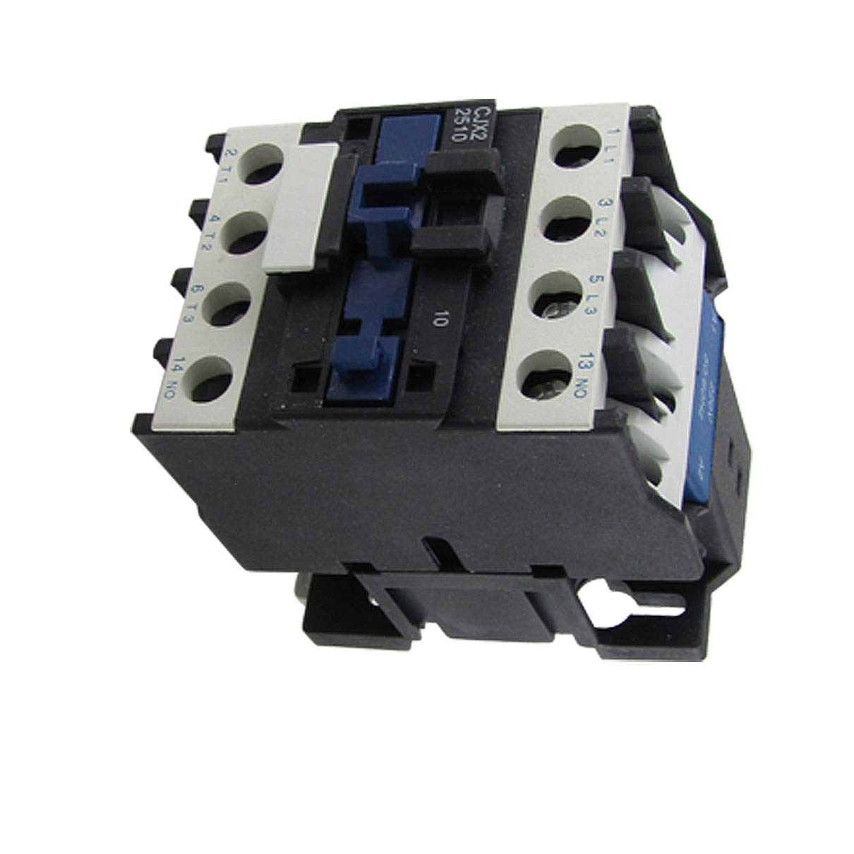
Figure 1: Aexit CJX2-2510 AC Contactor. This image displays the Aexit CJX2-2510 AC Contactor, highlighting its compact design and terminal layout for electrical connections.
2. Safety Information
WARNING: Electrical shock hazard. Installation and maintenance should only be performed by qualified personnel.
- Always disconnect power before installing, servicing, or removing the contactor.
- Ensure all wiring complies with local and national electrical codes.
- Verify correct voltage and current ratings before connecting the contactor to a circuit.
- Do not operate the contactor if it appears damaged.
- Use appropriate personal protective equipment (PPE) when working with electrical systems.
3. Product Features
- Model: CJX2-2510
- Contact Type: 3 Pole, Normally Open (NO)
- Application: Widely used for long-distance connecting and breaking circuits, frequent starting, and controlling AC electric motors.
- Expandability: Contacts can be assembled into a modular auxiliary contact group, air delayer, mechanical interlocking institutions, and other accessories.
- Standards Compliance: Compatible with IEC 60947.4, NFC 63110, VDE0660, GB14048.4 quality standards.
- Efficiency: Features low power consumption, light weight, long service life, and reliable operation.
4. Technical Specifications
| Parameter | Value |
|---|---|
| Product Name | AC Contactor |
| Model Number | CJX2-2510 |
| AC1, AC2 Voltage | 220VAC, 50Hz / 60Hz |
| Insulation Current (Ui) | 660V |
| Thermal Current Ith (Ith) | 32A |
| AC-3 Voltage | 660V |
| Rated Operational Current (Ie) | 10.6A |
| Controlled Power (Pe) | 9kW |
| Number of Contacts | 3P+NO (3 Pole + 1 Normally Open Auxiliary Contact) |
| Overall Size (Approx.) | 98 x 55 x 78mm / 3.85'' x 2.2'' x 3'' (L*W*H) |
| Material | Plastic, Metal, Electrical Parts |
| Main Color | Black |
| Net Weight | 332g |
| Manufacturer | Aexit |
5. Installation and Setup
Proper installation is critical for the safe and reliable operation of the AC contactor. It is strongly recommended that installation be performed by a qualified electrician.
5.1 Mounting
- Mount the contactor securely on a DIN rail or a suitable mounting plate within an electrical enclosure.
- Ensure adequate ventilation around the contactor to prevent overheating.
- Maintain proper clearance from other components to allow for heat dissipation and future access.
5.2 Wiring
- Power Circuit: Connect the main power supply to the L1, L2, L3 terminals and the motor load to the T1, T2, T3 terminals. Ensure correct phase sequence.
- Control Circuit: Connect the control voltage (220VAC, 50/60Hz) to the A1 and A2 coil terminals. This circuit energizes the coil to close the main contacts.
- Auxiliary Contacts: The CJX2-2510 includes one Normally Open (NO) auxiliary contact. This can be used for interlocking, signaling, or other control functions. Connect control wiring to these terminals as required by your application.
- Use appropriately sized wires for both power and control circuits, considering the current ratings and local electrical codes.
- Tighten all terminal screws to the recommended torque to ensure secure electrical connections and prevent loose contacts.
6. Operation
The Aexit CJX2-2510 AC Contactor operates by energizing its coil, which in turn closes the main power contacts, allowing current to flow to the connected load (e.g., an AC motor). When the coil is de-energized, the main contacts open, disconnecting the load from the power supply.
- Energizing the Coil: Apply the rated control voltage (220VAC, 50/60Hz) across the A1 and A2 terminals. This will cause the contactor to pull in, closing the main power contacts and the NO auxiliary contact.
- De-energizing the Coil: Remove the control voltage from the A1 and A2 terminals. The contactor will release, opening the main power contacts and the NO auxiliary contact.
- The contactor is designed for frequent switching operations, making it suitable for applications requiring repeated starting and stopping of motors.
7. Maintenance
Regular maintenance helps ensure the longevity and reliable performance of the AC contactor.
- Visual Inspection: Periodically inspect the contactor for any signs of physical damage, discoloration, or excessive wear.
- Terminal Connections: Check all terminal screws for tightness. Loose connections can lead to overheating and arcing.
- Cleaning: Keep the contactor free from dust, dirt, and moisture. Use a dry, soft cloth for cleaning. Do not use solvents.
- Contact Wear: While designed for long life, excessive arcing or frequent overloads can accelerate contact wear. If contacts appear heavily pitted or eroded, consider replacement.
- Operating Environment: Ensure the operating environment remains within specified temperature and humidity ranges.
8. Troubleshooting
This section provides guidance for common issues. For complex problems, consult a qualified electrician.
8.1 Contactor Does Not Engage
- No Control Voltage: Check if the correct control voltage (220VAC) is applied to terminals A1 and A2.
- Incorrect Wiring: Verify all control circuit wiring according to the schematic.
- Coil Failure: The coil may be open-circuited or short-circuited. Test the coil resistance with a multimeter (power disconnected).
- Mechanical Obstruction: Check for any foreign objects preventing the armature from moving freely.
8.2 Contactor Overheats
- Overload: The load current may exceed the contactor's rated operational current (10.6A). Reduce the load or use a higher-rated contactor.
- Loose Connections: Tighten all power circuit terminal screws.
- Poor Ventilation: Ensure adequate airflow around the contactor.
- Incorrect Control Voltage: If the control voltage is too low, the coil may not pull in firmly, leading to chattering and overheating. If too high, the coil itself may overheat.
8.3 Noisy Operation (Chattering)
- Low Control Voltage: Ensure the control voltage is stable and within the specified range.
- Mechanical Issues: Check for dirt or debris on the pole faces of the armature.
- Shading Coil Damage: A damaged shading coil can cause excessive hum.
9. Warranty and Support
For warranty information or technical support regarding the Aexit CJX2-2510 AC Contactor, please contact the manufacturer or your authorized distributor. Keep your purchase receipt or proof of purchase for warranty claims.
Manufacturer: Aexit