
Hereta LNK-INJ301
Hereta Hardened Industrial Gigabit PoE+ Injector User Manual
Model: LNK-INJ301
1. Product Overview
The Hereta Hardened Industrial Gigabit PoE+ Injector (Model LNK-INJ301) is a robust power sourcing equipment designed to provide both data and power over a single Ethernet cable to IEEE 802.3af/at compliant devices. Engineered for demanding industrial environments, it supports Gigabit Ethernet speeds and operates reliably across a wide temperature range.

Figure 1: Hereta Hardened Industrial Gigabit PoE+ Injector (Model LNK-INJ301).
2. Safety Information
Please read and understand all instructions before installing or operating this device. Failure to do so may result in injury, damage to the device, or property damage.
- Ensure proper grounding to prevent electrical shock.
- Do not expose the device to water or excessive moisture.
- Operate within the specified temperature range (-40°C to 80°C).
- Use only approved power supplies (12-48VDC).
- Do not attempt to open or repair the device. Refer servicing to qualified personnel.
- Disconnect power before cleaning or maintenance.
3. Package Contents
Verify that all items are present in the package:
- 1 x Hereta Hardened Gigabit High Power PoE Injector
- 1 x DIN-Rail bracket (pre-installed)
- 1 x Wall mount bracket
4. Key Features
- Ports: 1 RJ45 Ethernet Data Input Port + 1 RJ45 Power Over Ethernet Output Port (Data + Power).
- PoE Standard: Supports IEEE 802.3at Power over Ethernet (PoE+) Power Sourcing Equipment.
- Ethernet Speed: Supports 10/100/1000Base-TX.
- Indicators: Extensive LED indicators for PoE diagnostics.
- Power Input: Wide 12-48VDC input, requiring a 48VDC power supply for PoE output.
- Mounting: DIN-Rail bracket installed, with an included wall mount bracket for versatile installation.
- Durability: Environmentally hardened, operating temperature range from -40°C to 80°C (-40°F to 176°F).

Figure 2: Key features of the Hereta PoE Injector, highlighting its industrial design and capabilities.
5. Product Interface and Indicators
The PoE injector features clearly labeled ports and LED indicators for easy setup and monitoring.
- PoE+ OUT Port: Connects to the PoE-powered device (PD) such as an IP camera or wireless access point. This port delivers both data and power.
- Ethernet Port: Connects to your network switch, router, or NVR for data input.
- PWR LED: Indicates power status. Green when power is supplied.
- PoE LED: Indicates PoE status. Green when PoE power is being delivered to a connected device.
- V+/V- Terminal: Power input terminal for 12-48VDC power supply.

Figure 3: Front panel layout with PoE+ OUT, Ethernet ports, PWR and PoE LEDs, and DC power input.
6. Setup and Installation
Follow these steps to install and set up your Hereta PoE+ Injector:
- Mounting:
- DIN-Rail Mount: The injector comes with a pre-installed DIN-Rail bracket. Simply clip the device onto a standard DIN rail.
- Wall Mount: If wall mounting is preferred, remove the DIN-Rail bracket and use the included wall mount bracket to secure the device to a flat surface using appropriate screws (not included).

Figure 4: Installation methods: DIN-Rail and Wall Mount.
- Power Connection: Connect a 12-48VDC power supply (not included) to the V+/V- terminal block. Ensure correct polarity. The PWR LED will illuminate green once power is supplied.
- Data Input Connection: Connect an Ethernet cable from your network switch, router, or NVR to the "Ethernet" port on the injector.
- PoE Output Connection: Connect an Ethernet cable from the "PoE+ OUT" port on the injector to your IEEE 802.3af/at compliant PoE-powered device (PD). The PoE LED will illuminate green when power is successfully delivered to the PD.

Figure 5: Typical connection diagram for the PoE Injector.
7. Operating Instructions
Once properly installed and connected, the Hereta PoE+ Injector operates automatically. It detects the presence of an IEEE 802.3af/at compliant device and supplies the necessary power.
- Power On: Ensure the 12-48VDC power supply is connected and active. The PWR LED should be green.
- Device Connection: Connect your PoE-powered device to the PoE+ OUT port. The injector will negotiate power with the device.
- PoE Active: When a compatible PoE device is detected and powered, the PoE LED will turn green. If the LED is off, check the device connection and ensure it is PoE compliant.
- Data Transmission: Data will pass through the injector between your network and the connected PoE device.
Video 1: A demonstration of the Hereta PoE Injector, showcasing its physical appearance and ports.
8. Applications
The Hereta Hardened Industrial Gigabit PoE+ Injector is ideal for various applications requiring reliable power and data transmission in challenging environments:
- CCTV Security Transmission: Powering IP cameras in surveillance systems.
- Wireless AP Deployment: Providing power to wireless access points in remote or outdoor locations.
- IP Fixed Phones: Supplying power to VoIP phones in offices or industrial settings.
- Industrial Automation: Connecting and powering various network-enabled industrial sensors and devices.
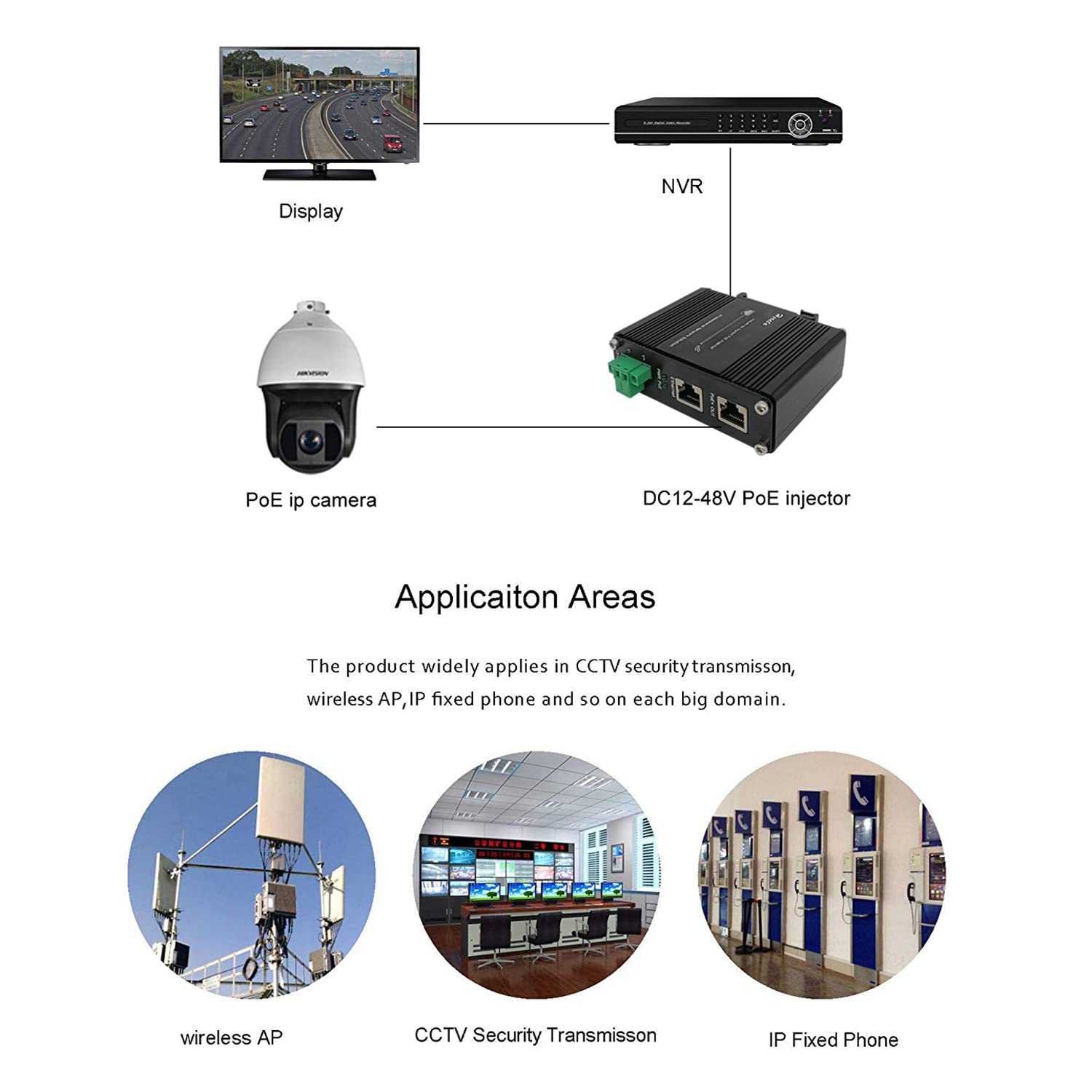
Figure 6: Common application scenarios for the Hereta PoE Injector.
9. Maintenance
The Hereta PoE+ Injector is designed for minimal maintenance due to its hardened industrial design. However, periodic checks can ensure optimal performance:
- Cleaning: Gently wipe the exterior with a dry, soft cloth to remove dust. Do not use liquid cleaners or solvents.
- Cable Inspection: Periodically inspect all connected Ethernet and power cables for damage or loose connections.
- Environmental Check: Ensure the operating environment remains within the specified temperature and humidity ranges. Avoid placing the device near heat sources or in direct sunlight.
- Firmware Updates: Check the manufacturer's website for any available firmware updates, though this device typically does not require user-initiated firmware updates.

Figure 7: The industrial design allows operation in harsh environmental conditions.
10. Troubleshooting
If you encounter issues with your PoE+ Injector, refer to the following common troubleshooting steps:
| Problem | Possible Cause | Solution |
|---|---|---|
| No Power (PWR LED Off) | No power supply connected or faulty power supply/cable. Incorrect voltage. |
|
| No PoE Output (PoE LED Off) | Connected device is not PoE compliant or faulty. Incorrect cable connection. Overload. |
|
| No Data Transmission | Faulty Ethernet cable or network device. |
|
11. Specifications
| Feature | Description |
|---|---|
| Model Number | LNK-INJ301 |
| Ethernet Ports | 1 x RJ45 Data Input, 1 x RJ45 PoE+ Output |
| Ethernet Standard | 10/100/1000Base-TX |
| PoE Standard | IEEE 802.3at (PoE+) |
| PoE Power Output | Up to 30W |
| Power Input | 12-48VDC (Terminal Block) |
| Operating Temperature | -40°C to 80°C (-40°F to 176°F) |
| Product Dimensions | 3.8 x 2.8 x 1.2 inches (9.65 x 7.11 x 3.05 cm) |
| Weight | 8.82 ounces (250 g) |
| Mounting Options | DIN-Rail, Wall Mount |

Figure 8: Physical dimensions of the PoE Injector.
12. Warranty and Support
For warranty information, technical support, or further inquiries, please refer to the official Hereta website or contact their customer service directly. Keep your purchase receipt for warranty claims.
You can visit the Hereta Store on Amazon for more product information and support resources.
Related documentsLNK-INJ301


Ask a question about this manual
Ask about setup, troubleshooting, compatibility, parts, safety, or missing instructions. Manuals+ will review the question and use this page’s manual context to help answer it.