
1. Introduction
This manual provides detailed instructions for the installation, operation, and maintenance of the Reland Sung XH-M601 12V Battery Charging Control Board. This module is designed to intelligently manage the charging process of 12V storage batteries, ensuring automatic charging and disconnection based on set voltage thresholds.
2. Product Overview
The XH-M601 is a compact and efficient control module for 12V battery charging systems. It features adjustable potentiometers to set the start and stop charging voltages, providing precise control over the battery's charge cycle. The board includes a relay for switching the charging power and screw terminals for easy connection.
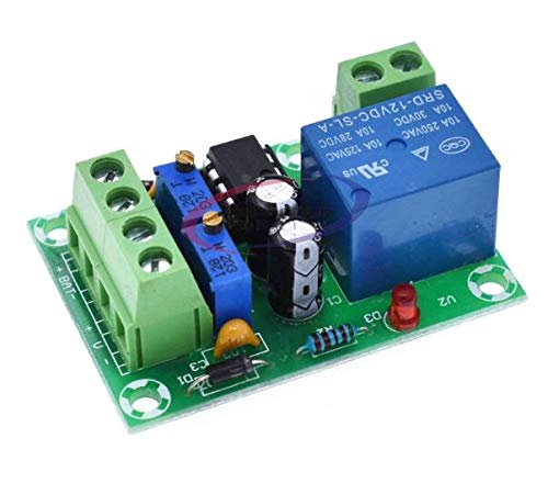
Figure 2.1: Top-down view of the XH-M601 Battery Charging Control Board, showing the relay, potentiometers, and terminal blocks.
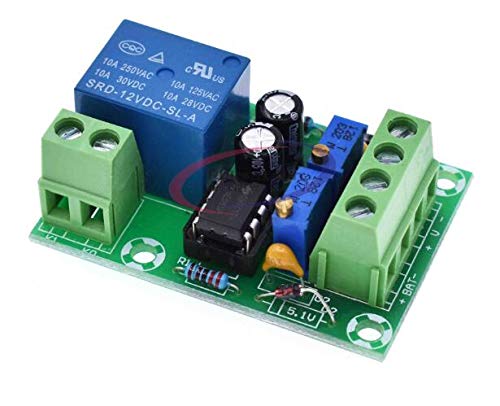
Figure 2.2: Angled view of the XH-M601 board, highlighting the input/output terminals and main components.

Figure 2.3: Bottom view of the XH-M601 board, showing the printed circuit board traces and solder points.
3. Specifications
| Product Name | 12V Charger Power Control Board |
| Model | XH-M601 |
| Power Supply Voltage | 13.8V - 14.8V |
| Relay Operating Voltage (Start Charging) | 12.4V |
| Relay Disconnect Voltage (Stop Charging) | 14.8V |
| Voltage Tolerance | +/-0.1V |
| Voltage Detection Method | DC Voltmeter |
| Compatible Battery Type | 12V Storage Battery |
| Adjustable Parameters | RP1 (Start Charging Voltage), RP2 (Stop Charging Voltage) |
| Dimensions | 50mm x 32mm x 18mm |
4. Setup and Installation
Before installation, ensure all power sources are disconnected to prevent electrical shock or damage to the module and battery. The XH-M601 board is designed for integration into a 12V battery charging circuit.
- Identify Terminals: The board features screw terminals for connecting the battery and the charging power source. Refer to the markings on the PCB (e.g., "+BAT-", "+IN-").
- Connect Battery: Connect the 12V storage battery to the designated battery terminals on the XH-M601 board. Ensure correct polarity (+ to + and - to -).
- Connect Charger: Connect your 12V charging power supply (e.g., a DC power adapter or solar charge controller output) to the input terminals of the XH-M601 board. The relay on the board will switch this power to the battery.
- Secure Connections: Ensure all wire connections are secure and tight to prevent intermittent operation or arcing.
- Initial Power-Up: Once all connections are verified, apply power to the charging source. The board will monitor the battery voltage.
Important Safety Note: Always double-check wiring before applying power. Incorrect wiring can damage the module, battery, or charging source.
5. Operation and Adjustment
The XH-M601 board uses two potentiometers, RP1 and RP2, to set the charging thresholds.
- RP1 (Start Charging Voltage Adjustment): This potentiometer sets the lower voltage threshold at which the relay will engage, initiating the charging process for the 12V storage battery.
- Turning RP1 clockwise increases the start charging voltage.
- Turning RP1 counter-clockwise decreases the start charging voltage.
- RP2 (Disconnect Charging Voltage Adjustment): This potentiometer sets the upper voltage threshold at which the relay will disengage, stopping the charging process to prevent overcharging the 12V storage battery.
- Turning RP2 clockwise increases the disconnect charging voltage.
- Turning RP2 counter-clockwise decreases the disconnect charging voltage.
Adjustment Procedure:
- Connect the board and battery as described in Section 4.
- Use a reliable DC voltmeter to monitor the battery voltage directly.
- To set the start charging voltage (RP1), allow the battery voltage to drop to your desired minimum level. Then, slowly adjust RP1 until the relay clicks and charging begins.
- To set the disconnect charging voltage (RP2), allow the battery to charge until it reaches your desired maximum level. Then, slowly adjust RP2 until the relay clicks and charging stops.
- It is recommended to perform these adjustments with the battery at the desired voltage levels for accurate calibration.
6. Maintenance
The XH-M601 board is designed for reliable operation with minimal maintenance. However, periodic checks can help ensure its longevity and proper function:
- Keep Clean and Dry: Ensure the board is kept free from dust, dirt, and moisture. Use a soft, dry brush or compressed air for cleaning if necessary.
- Inspect Connections: Periodically check all wire connections to the screw terminals to ensure they remain tight and free from corrosion.
- Environmental Conditions: Operate the module within its specified temperature and humidity ranges to prevent damage.
- Visual Inspection: Look for any signs of physical damage, burnt components, or loose parts.
7. Troubleshooting
If you encounter issues with the XH-M601 board, consider the following troubleshooting steps:
- Module Not Powering On:
- Verify that the input power supply voltage is within the specified range (13.8V-14.8V for the board's own power, and the battery voltage for monitoring).
- Check all power connections for correct polarity and secure contact.
- Battery Not Charging:
- Ensure the battery voltage is below the RP1 (start charging) threshold.
- Check the connection from the charging source to the board's input terminals.
- Verify the relay is clicking when the voltage drops below RP1. If not, RP1 might be set too low or the relay might be faulty.
- Battery Overcharging:
- Ensure the RP2 (disconnect charging) threshold is set correctly and is below the battery's maximum safe voltage.
- Verify the relay is disengaging when the voltage reaches RP2. If not, RP2 might be set too high or the relay might be faulty.
- Inaccurate Voltage Readings:
- Ensure your external voltmeter is calibrated and accurate.
- Check for loose connections that could cause voltage drops.
If the problem persists after these steps, contact the seller for further assistance.
8. Warranty and Support
Specific warranty information for the Reland Sung XH-M601 Battery Charging Control Board is not provided in this manual. For details regarding warranty coverage, return policies, or technical support, please refer to the product listing on the point of purchase or contact the seller directly.
When contacting support, please provide your purchase details, the product model (XH-M601), and a clear description of the issue you are experiencing.
