
Steelman 60635
STEELMAN 60635 Wireless ChassisEAR Diagnostic Device Kit
Instruction Manual
1. Introduction
The STEELMAN 60635 Wireless ChassisEAR Diagnostic Device Kit is engineered to assist in pinpointing the source of various noises such as squeaks, rattles, and other errant sounds originating from a vehicle's engine, axles, and chassis. This device functions as a high-powered wireless stethoscope, enabling technicians and enthusiasts to diagnose issues in components like fuel injectors, bearings, gears, suspensions, transmissions, differentials, and CV joints, even during vehicle operation.
The kit utilizes independent wireless transmitters that relay sound to a central receiver, allowing for real-time acoustic analysis. This eliminates the need for cumbersome wired connections, providing flexibility and ease of use in a variety of automotive diagnostic scenarios.
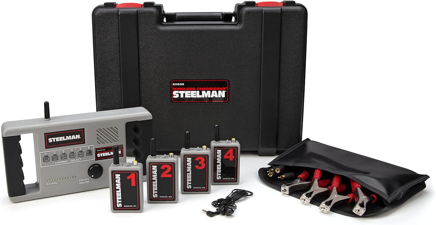
Figure 1: Overview of the STEELMAN 60635 Wireless ChassisEAR Diagnostic Device Kit.
2. What's in the Box
Your STEELMAN 60635 Wireless ChassisEAR kit includes the following components:
- 1 x Receiver Unit
- 4 x Wireless Transmitters (numbered 1-4)
- 1 x Set of Mini Earphones
- 4 x Cable-Leads/Microphone Clamps
- 12 x Nylon Straps
- 12 x Hook-and-Loop Straps
- 6 x AA Batteries (for receiver)
- 16 x AAA Batteries (4 for each transmitter)
- 1 x Organizer Pouch
- 1 x Location Identifier Note Pad
- 1 x Instruction Manual (this document)
- 1 x Blow-Molded Storage Case
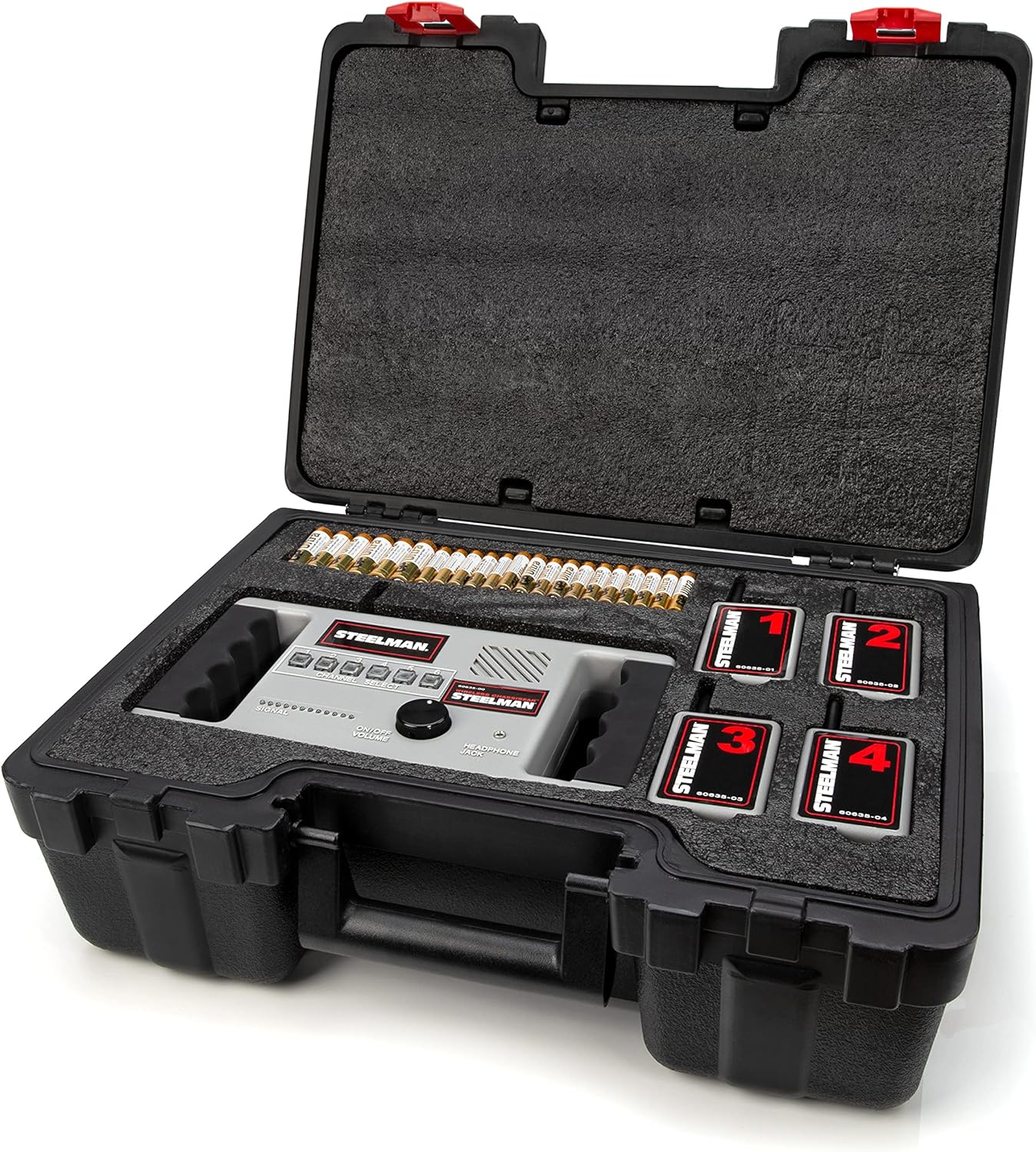
Figure 2: Kit contents within the storage case.
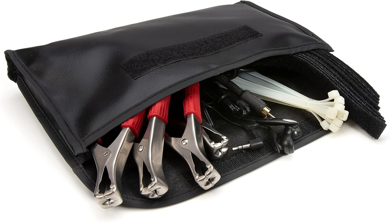
Figure 3: Organizer pouch with accessories.
3. Setup
3.1 Battery Installation
- Receiver Unit: Open the battery compartment on the back of the receiver. Insert 6 AA batteries, ensuring correct polarity (+/-). Close the compartment securely.
- Transmitters: Open the battery compartment on each of the 4 transmitters. Insert 4 AAA batteries into each transmitter, ensuring correct polarity (+/-). Close the compartments securely.
3.2 Transmitter Placement
Each transmitter is equipped with built-in clips and magnets for easy attachment to various vehicle components. For more secure or flexible placement, utilize the included nylon hook-and-loop straps.
- Attach transmitters to suspected noise sources such as axles, suspension components, engine parts, or chassis points.
- Ensure the transmitters are securely fastened to prevent dislodging during vehicle movement.

Figure 4: Individual transmitter with microphone clamp.

Figure 5: Transmitter attached to a vehicle component.
3.3 Connecting Microphone Clamps
Connect one end of each cable-lead/microphone clamp to the corresponding transmitter's input jack. Secure the clamp end to the specific area where you suspect the noise is originating. The clamps are designed to pick up vibrations and convert them into audible signals.
3.4 Connecting Earphones
For private listening and clearer sound isolation, plug the mini earphones into the 3.5mm headphone jack located on the receiver unit. Alternatively, you can use the built-in speaker.
4. Operating Instructions
4.1 Powering On/Off
To power on the receiver unit, rotate the ON/OFF VOLUME knob clockwise until it clicks and the signal LEDs illuminate. To power off, rotate the knob counter-clockwise until it clicks off.
4.2 Channel Selection
The receiver unit features six channel select buttons (1-6). Press the corresponding button to select the channel linked to a specific transmitter. The illuminated button indicates the active channel. You can switch between channels to isolate sounds from different locations. Pressing an active channel button again will mute that channel.

Figure 6: Receiver unit controls.
4.3 Interpreting Signal Strength LEDs
The receiver unit has a series of LED lights that indicate the signal strength of the active channel. More illuminated LEDs signify a stronger signal from the selected transmitter, indicating clear reception of the noise.
4.4 Driving for Diagnosis
Once transmitters are securely placed and the receiver is ready, operate the vehicle under conditions that typically produce the noise. Listen carefully through the earphones or built-in speaker, switching between channels to identify which transmitter is picking up the most prominent sound. This helps in pinpointing the exact location of the noise source.
5. Maintenance
5.1 Cleaning
Wipe down the receiver and transmitters with a soft, damp cloth after each use. Avoid using harsh chemicals or abrasive cleaners, which can damage the unit's finish or internal components.
5.2 Battery Replacement
Replace batteries when the signal strength LEDs on the receiver become consistently low or when the sound quality degrades. Always replace all batteries in a unit (either receiver or transmitter) at the same time with new ones of the specified type (AA for receiver, AAA for transmitters).
5.3 Storage
Store the STEELMAN 60635 kit in its blow-molded storage case in a cool, dry place when not in use. Remove all batteries if the device will not be used for an extended period to prevent battery leakage and potential damage.
6. Troubleshooting
6.1 No Sound or Weak Signal
- Check battery levels in both the receiver and the active transmitter. Replace if necessary.
- Ensure the microphone clamp is securely connected to the transmitter and the suspected noise source.
- Verify that the correct channel is selected on the receiver.
- Confirm that the volume knob on the receiver is turned up.
- Ensure earphones are fully plugged into the jack, if used.
6.2 Interference
- Move away from strong electromagnetic fields or other wireless devices that might cause interference.
- Ensure transmitters are not placed too close to large metal objects that could block the signal.
6.3 Transmitter Issues
- If a specific transmitter consistently fails, try swapping its batteries with known good ones.
- Inspect the cable-lead/microphone clamp for any visible damage or loose connections.
6.4 Compatibility Note
Important: The STEELMAN 60635 series transmitters and receiver are not compatible with older STEELMAN 97202 ChassisEAR models due to operating on different frequencies.
7. Specifications
| Feature | Detail |
|---|---|
| Model Number | 60635 |
| Brand | Steelman |
| Manufacturer | JS Products |
| Item Weight | 7.88 pounds |
| Product Dimensions | 17.5 x 6.75 x 13 inches |
| Receiver Batteries | 6 AA batteries (included) |
| Transmitter Batteries | 16 AAA batteries (included, 4 per transmitter) |
| Transmitter to Receiver Range | Up to 50 feet |
| Channels | 4 independent channels (expandable to 6) |
| Audio Output | Built-in speaker, 3.5mm headphone jack |

Figure 7: Product diagram with key features and specifications.
8. Warranty and Support
For information regarding product warranty, technical support, or service, please refer to the official Steelman website or contact their customer service department. Keep your purchase receipt as proof of purchase for any warranty claims.
Steelman Customer Service: Visit SteelmanTools.com
Ask a question about this manual
Ask about setup, troubleshooting, compatibility, parts, safety, or missing instructions. Manuals+ will review the question and use this page’s manual context to help answer it.