1. Introduction
This manual provides detailed instructions for assembling and operating the MiOYOOW 3-Set Heart Shaped DIY LED Light Kits. This kit is designed for individuals interested in learning electronics and practicing soldering skills. It includes components for three heart-shaped LED circuits, each featuring a different LED color (Red, Green, White).
What's Included
- 3 x Heart-shaped PCB boards
- Electronic components for three circuits (resistors, capacitors, ICs, transistors, potentiometers, LEDs, power switches)
- Red, Green, and White LEDs for colorful projects
- Operating voltage: DC 4-6V
- Finished product size: 1.99" x 1.99"
Note: This product is a DIY kit and requires assembly. Basic electronic knowledge and soldering ability are necessary.
2. Safety Information
- Always wear appropriate safety glasses when soldering.
- Ensure adequate ventilation in your workspace to avoid inhaling solder fumes.
- Use a stable, heat-resistant surface for soldering.
- Keep soldering irons and hot components away from flammable materials.
- Always disconnect power before making any adjustments or repairs to the circuit.
- This kit contains small parts and is not suitable for young children without adult supervision.
Required Tools (Not Included)
- Soldering Iron
- Solder wire
- Wire cutters/strippers
- Small screwdriver (for potentiometer adjustment)
- Multimeter (recommended for checking components and connections)
- Safety glasses
- Ventilation fan
Power Source: A DC 4-6V power source is required (e.g., 3-4 AA batteries or a compatible USB power supply). A battery holder or USB cable is not included in the kit and must be supplied by the user.
3. Components List
Refer to the image below for a visual representation of the components and their corresponding PCB markers.

Image: All components included in the kit, with a detailed list.
| NO. | Component Name | PCB Marker | Parameter | QTY |
|---|---|---|---|---|
| 1 | Metal Film Resistor | R5 | 22R | 1 |
| 2 | Metal Film Resistor | R6 | 10K | 1 |
| 3 | Metal Film Resistor | R1,R2,R4 | 47K | 3 |
| 4 | Metal Film Resistor | R3 | 100K | 1 |
| 5 | Electrolytic Capacitor | C1 | 47UF | 1 |
| 6 | Potentiometer | VR1 | 50K | 1 |
| 7 | LM358 | U1 | DIP-8 | 1 |
| 8 | Power Switch | S1 | 6P | 1 |
| 9 | S8050 | Q1 | TO-92 | 1 |
| 10 | LED | LED1-LED22 | 5mm | 22 |
| 11 | PCB | 1 |
Resistor Color Codes
- Brown Black Orange: 10k Ohms (R6)
- Red Red Black: 22 Ohms (R5)
- Brown Black Yellow: 100k Ohms (R3)
- Yellow Violet Orange: 47k Ohms (R1, R2, R4)
Note: The provided manual may be black and white, making resistor identification difficult. Use the color codes above to correctly identify and place resistors.
4. Assembly Instructions
Follow these steps carefully to assemble your Heart Shaped LED DIY Kit. Pay close attention to component orientation.

Image: Visual guide for component installation.
- Install Resistors: Solder R3 (100K), R5 (22R), R6 (10K), and the three 47K resistors (R1, R2, R4) into their designated positions on the PCB. Resistors can be installed in any orientation.
- Install LM358 IC (U1): Carefully insert the LM358 integrated circuit. Ensure the notch on the IC matches the notch printed on the PCB silkscreen. Solder all pins.
- Install LEDs (LED1-LED22): Install the 22 LEDs. LEDs are polarized. The shorter lead (cathode) should be placed in the hole marked with a line or flat edge on the PCB. The longer lead (anode) goes into the unmarked hole.
- Install S8050 Transistor (Q1): Insert the S8050 transistor, ensuring its flat side aligns with the flat marking on the PCB. Solder the three pins.
- Install Electrolytic Capacitor (C1): The electrolytic capacitor is polarized. The side with the white stripe indicates the negative (-) lead. Align this with the negative marking on the PCB. Solder the leads.
- Install Potentiometer (VR1): Insert the potentiometer and solder its pins.
- Install Power Switch (S1): Insert the power switch and solder its pins.
- Connect Power: Solder your DC 4-6V power source wires to the designated "POWER" pads on the PCB (DC4-6V). Ensure correct polarity: positive (+) to the marked positive pad, negative (-) to the marked negative pad.
Tip for LEDs: To ensure LEDs sit flat, solder one lead first, then gently reheat and adjust the LED while applying light pressure to seat it properly before soldering the second lead.
5. Operating Instructions
Once assembled and connected to a DC 4-6V power source, the heart-shaped LED circuit will begin to flash.
- Power On: Flip the power switch (S1) to the ON position. The LEDs should begin to flash.
- Adjust Flashing Speed: Use a small screwdriver to turn the potentiometer (VR1). Turning the potentiometer will adjust the rate at which the LEDs flash. After adjusting, you may need to toggle the power switch off and on again for the new speed to take effect.

Image: A fully assembled heart-shaped LED circuit board.

Image: Example of the three different colored heart-shaped LED kits.
6. Maintenance
- Keep the circuit board clean and free from dust and debris.
- Avoid exposing the circuit to moisture or extreme temperatures.
- Periodically check solder joints for any signs of cracking or corrosion. Re-solder if necessary.
- If using batteries, replace them when the LED brightness diminishes or flashing becomes inconsistent.
Cleaning
Use a soft, dry brush or compressed air to remove dust. For stubborn dirt, a cotton swab lightly dampened with isopropyl alcohol can be used, ensuring the circuit is completely dry before reapplying power.
7. Troubleshooting
| Problem | Possible Cause | Solution |
|---|---|---|
| LEDs do not light up |
|
|
| Some LEDs do not light up |
|
|
| Flashing speed cannot be adjusted |
|
|
| Circuit board gets hot |
|
|
8. Technical Specifications
- Model Number: Heart Shaped LED DIY Kit
- Operating Voltage: DC 4-6V
- Dimensions: 1.99 x 1.99 inches (approx. 50 x 50 mm)
- Material: Copper (PCB)
- LED Colors: Red, Green, White (3-set includes one of each color)
- Included Components: Circuit board, resistors, capacitors, IC (LM358), transistor (S8050), potentiometer, power switch, LEDs.
- Item Weight: 0.81 ounces (per kit)
- Manufacturer: WHDTS
- Part Number: a90243
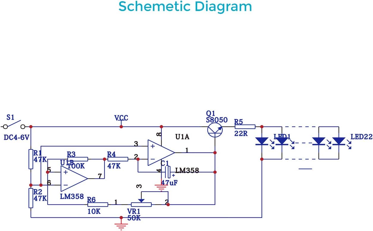
Image: Front and back view of the PCB board.

Image: Circuit schematic diagram.
9. Warranty and Support
This product is a DIY kit intended for educational and hobbyist use. Due to the nature of self-assembly and soldering, specific warranty terms may vary. Please refer to the seller's return policy for details on defective or missing components upon receipt.
For technical assistance or inquiries regarding missing/defective parts, please contact MiOYOOW customer support directly through the platform where the product was purchased.
Note: Damage resulting from improper assembly, incorrect power supply, or misuse is not covered.


