
1. Introduction
The DollaTek MAX31865 module is designed to interface with Resistance Temperature Detectors (RTDs) such as PT100 and PT1000 sensors. It provides a convenient way to read temperature data with high accuracy, supporting 2, 3, or 4-wire RTD configurations. This module communicates via SPI and is compatible with various microcontrollers, including Arduino. This manual provides essential information for setting up, operating, and maintaining your MAX31865 module.
2. Product Overview
The MAX31865 module addresses all your RTD needs and can compensate for 3 or 4-wire RTDs for improved accuracy. This breakout board is 5V compliant, featuring a 3.3V regulator and level shifting, making it compatible with any Arduino or microcontroller.
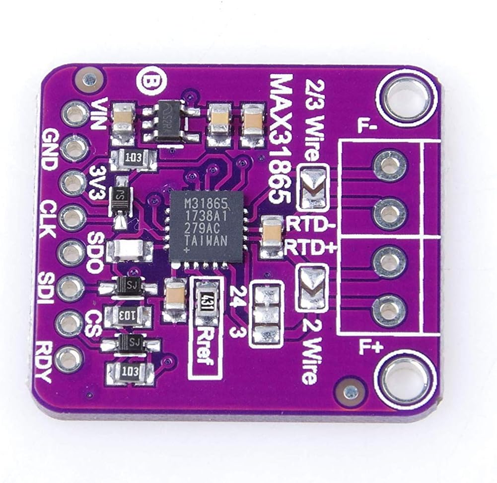
Figure 1: Top view of the DollaTek MAX31865 RTD Temperature Sensor Amplifier Module.
2.1. Package Contents
The package typically includes:
- 1 x DollaTek MAX31865 RTD Temperature Sensor Amplifier Module
- Pin headers for connection
- Screw terminals for RTD connection

Figure 2: DollaTek MAX31865 module with included pin headers and screw terminals.
3. Features
- Supports PT100 and PT1000 RTD sensors.
- Compensates for 3 or 4-wire RTDs for enhanced accuracy.
- Compatible with any microcontroller via SPI communication.
- Features a 3.3V regulator and level shifting for 5V compatibility.
- Designed for use with 2, 3, or 4-wire RTD configurations.
4. Setup
4.1. Pinout
The module features several pins for power, communication, and RTD connection. Refer to the image below for pin identification:

Figure 3: Bottom view of the DollaTek MAX31865 module with pin labels.
- VIN: Power input (3V-5V DC)
- GND: Ground
- 3V3: 3.3V regulated output
- CLK: SPI Clock
- SDO: SPI Data Out (Master In, Slave Out)
- SDI: SPI Data In (Master Out, Slave In)
- CS: Chip Select
- RDY: Ready (optional, indicates data ready)
- RTD+, RTD-, F+, F-: RTD sensor connections
4.2. Connecting an RTD Sensor
The MAX31865 supports 2, 3, and 4-wire RTD configurations. Connect your RTD sensor to the screw terminals provided on the module. Ensure correct polarity and wiring based on your RTD type.
- 2-wire RTD: Connect both RTD wires to RTD+ and RTD-. Short F+ to RTD+ and F- to RTD-.
- 3-wire RTD: Connect one sense wire to RTD+, one return wire to RTD-, and the third wire to F+. Short F- to RTD-.
- 4-wire RTD: Connect two sense wires to RTD+ and F+, and two return wires to RTD- and F-.
4.3. Configuring for PT1000 Sensors
By default, the module is configured for PT100 RTD sensors. To use a PT1000 sensor, you must replace the reference resistor (Rref) on the board. Locate the resistor labeled 'Rref' (often marked '430' for 430Ω for PT100). Replace this resistor with a 4300Ω (4301) resistor. The recommended package size is 0805 for surface-mount components.

Figure 4: Location of the Rref resistor for PT1000 configuration.
4.4. Connecting to a Microcontroller
Connect the module to your microcontroller using the SPI interface:
- VIN to 3.3V or 5V power supply of your microcontroller (the module has a 3.3V regulator).
- GND to microcontroller Ground.
- CLK to microcontroller SPI Clock pin.
- SDO to microcontroller SPI MISO (Master In, Slave Out) pin.
- SDI to microcontroller SPI MOSI (Master Out, Slave In) pin.
- CS to any digital pin on your microcontroller configured as Chip Select.
5. Operating Instructions
After connecting the module and RTD sensor, you can begin reading temperature data. The MAX31865 communicates via SPI to provide the resistance ratio of the RTD, which can then be converted into a temperature reading.
Most microcontrollers, such as Arduino, have libraries available to simplify interaction with the MAX31865. These libraries typically handle the SPI communication and the conversion of resistance readings to temperature (e.g., Celsius or Fahrenheit). Refer to the documentation of your chosen library for specific code examples and usage.
Ensure that your software configuration matches your hardware setup, especially regarding the RTD type (PT100 or PT1000) and the number of wires used (2, 3, or 4-wire compensation settings).
6. Maintenance
- Keep the module in a dry environment to prevent moisture damage.
- Avoid exposing the module to extreme temperatures or direct sunlight.
- Handle the module with care to prevent physical damage to components or solder joints.
- Periodically inspect connections for looseness or corrosion.
- Always discharge static electricity before handling the module to prevent damage to sensitive electronic components.
7. Troubleshooting
- No temperature reading or incorrect values:
- Check all wiring connections (power, ground, SPI, RTD).
- Verify that the RTD sensor is correctly connected for 2, 3, or 4-wire configuration.
- Ensure the correct Rref resistor is installed for your RTD type (PT100 or PT1000).
- Confirm that your software library is configured for the correct RTD type and wiring.
- Module not detected by microcontroller:
- Check power supply (VIN and GND).
- Verify SPI connections (CLK, SDO, SDI, CS).
- Ensure the Chip Select (CS) pin is correctly toggled by your software.
- Erratic readings:
- Check for electrical noise in the environment.
- Ensure RTD wires are shielded if running over long distances.
- Verify stable power supply to the module and microcontroller.
8. Specifications
| Feature | Description |
|---|---|
| Model Number | PT100 MAX31865 |
| Manufacturer | DollaTek |
| Dimensions | 10.3 x 6.9 x 0.4 cm |
| Weight | 6 grams |
| Compatible Devices | Microcontroller, Arduino |
| Development Environment | Arduino IDE (AVR/ESP32) |
| Special Feature | Compensation for 3 or 4-wire RTDs for improved accuracy |
| Connectivity Technology | SPI |
| UPC / GTIN | 742548987602 |
9. Warranty and Support
Warranty information for this product is not explicitly provided in the available data. For details regarding warranty coverage, technical support, or service, please contact your retailer or the manufacturer, DollaTek, directly. Ensure you have your purchase receipt and product model number (PT100 MAX31865) available when seeking support.