1. Introduction
This manual provides detailed instructions for the operation and maintenance of the Walfront JDS6600 DDS Signal Generator Counter. The JDS6600 is a dual-channel arbitrary waveform function generator and frequency meter, capable of producing various waveforms with high precision and stability. It is designed for use in factories, schools, research institutes, and laboratories.
2. Safety Information
- Ensure the power supply voltage matches the device's requirements.
- Do not operate the device in wet or damp conditions.
- Avoid exposing the device to direct sunlight or high temperatures.
- Do not attempt to disassemble or repair the device yourself. Refer to qualified personnel for service.
- Use only specified accessories and cables.
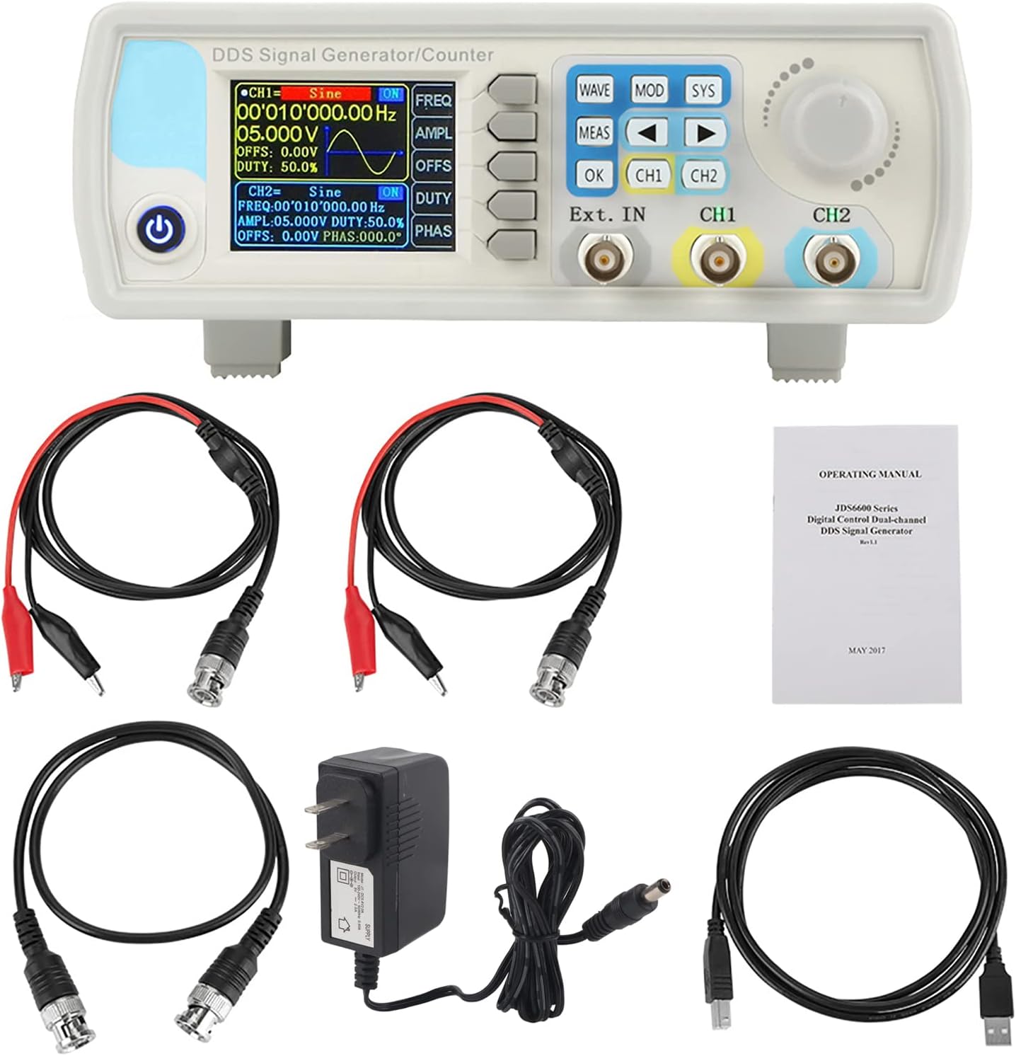
3. Package Contents
Verify that all items listed below are included in your package:
- 1 x JDS6600 DDS Signal Generator Counter Unit
- 2 x BNC to Alligator Clip Cables
- 1 x BNC to BNC Cable
- 1 x USB Cable
- 1 x Power Adapter
- 1 x Operating Manual
- 1 x CD (Software/Drivers)
4. Product Overview
4.1 Front Panel Layout
The front panel features a 2.4-inch TFT color LCD display, control buttons, a rotary encoder, and BNC output terminals for channels 1 and 2, as well as an external input.

4.2 Rear Panel Connections
The rear panel includes the TTL extension interface, USB communication port, and the DC 5V power supply input.

4.3 Display Interface
The 2.4-inch TFT color LCD displays parameters for both Channel 1 (CH1) and Channel 2 (CH2), including waveform type, frequency, amplitude, offset, and duty cycle. It also shows the current channel output status, a waveform display, and a soft-key menu bar for navigation.

4.4 Key Features
- Exquisite Waveform: 14-bit vertical resolution, 266MSa/s sampling rate. Sine frequency up to 60MHz, square up to 15MHz.
- Dual-Channel Output: Fully independent dual-channel operation with adjustable phase difference (0.1 degrees precision).
- Diverse Waveforms: Supports Sine, Square, Pulse (adjustable duty cycle, pulse width, period), Triangular, Partial Sine, CMOS, DC level, Half Wave, Full Wave, Positive Staircase, Anti-Ladder, Noise, Exponential Rise/Drop, Multi-Sonic, and 60 arbitrary waveforms.
- PC Software Control: Allows control of all machine functions and creation of arbitrary waveforms via standard PC software.
- Output Protection: Output short circuit protection for up to 60 seconds under load.
- High Accuracy: Utilizes large-scale integrated circuits and SMT technology for high reliability and precise bias adjustment (-9.99V to +9.99V).

5. Setup
5.1 Power Connection
Connect the provided DC 5V power adapter to the power input port on the rear panel of the JDS6600 unit. Plug the adapter into a suitable power outlet.
5.2 USB Connection (for PC Control)
To control the JDS6600 via PC software, connect the unit to your computer using the supplied USB cable. The USB port is located on the rear panel.
5.3 Output Connections
Connect BNC cables to the CH1 and CH2 output terminals on the front panel. These cables can then be connected to an oscilloscope, frequency counter, or other test equipment.
5.4 Software Installation
The JDS6600 comes with PC software that allows for comprehensive control and arbitrary waveform generation. Install the software from the provided CD or download the latest version from the manufacturer's website. Follow the on-screen instructions for driver and software installation.
6. Operating Instructions
6.1 Basic Operation
After connecting the power, press the power button to turn on the device. The display will show the default settings for CH1 and CH2. Use the CH1 and CH2 buttons to toggle the output of each channel on or off. The rotary encoder is used to navigate menus and adjust parameter values.
6.2 Waveform Selection and Parameter Adjustment
Press the WAVE button to cycle through available waveform types. Once a waveform is selected, use the dedicated function buttons (FREQ, AMPL, OFFS, DUTY, PHAS) to adjust its parameters. Turn the rotary encoder to change the values, and press OK to confirm.
6.3 System Settings
Press the SYS button to access system settings. Here you can save and load configurations, adjust sound and brightness, change the display language, and manage other system-wide preferences.
6.4 Modulation Modes
Press the MOD button to enter modulation mode. You can select various modulation types such as Sweep Frequency, Pulse Generator, and Burst. Use the arrow keys and rotary encoder to configure the modulation parameters.
6.5 Measurement Mode
The MEAS button allows you to use the device as a frequency counter for external signals. Connect the external signal to the 'Ext. IN' BNC port and configure the measurement settings via the menu.
6.6 PC Software Control
Once the PC software is installed and the device is connected via USB, you can control all functions from your computer. The software interface mirrors the device's controls, allowing for precise adjustments and the creation of custom arbitrary waveforms. This enables advanced signal generation and analysis.

7. Maintenance
- Keep the device clean and free from dust. Use a soft, dry cloth for cleaning.
- Avoid using abrasive cleaners or solvents that could damage the casing or display.
- Store the device in a cool, dry environment when not in use.
- Regularly check cables and connectors for any signs of wear or damage.
8. Troubleshooting
- No Power: Check the power adapter connection and ensure the power outlet is functional.
- No Signal Output: Verify that the correct channel (CH1 or CH2) is enabled and that parameters like amplitude and frequency are set appropriately. Check cable connections.
- PC Software Connection Issues: Ensure USB drivers are correctly installed (refer to Section 5.4). Check the COM port selection in the software.
- Incorrect Waveform Display: Confirm that the selected waveform type and parameters match your intended output.
9. Specifications
9.1 General Specifications
| Feature | Description |
|---|---|
| Display | 2.4 inch TFT color LCD |
| Store and Load | Quantity: 100 (00 to 99), Position: 00 to 99 (00 memory location is loaded by default as power on) |
| Arbitrary Wave | Quantity: 1 to 60 total (15 groups by default as power on) |
| Interface Mode | USB to serial interface |
| Extension Interface | With TTL level mode serial interface for user secondary development |
| Communication Speed | Standard 115200bps |
| Protocol | Using the command line, the protocol is public |
| Power Supply | DC5V±0.5V |
| Manufacturing Technology | Surface mount technology, large-scale integrated circuits, high reliability, long service life |
| Prompt Tone | Users can turn on or off by setting program |
| Operating Characteristics | All key operations, knob continuous adjustment |
| Environmental Conditions | Temperature: 0~40°C, Humidity: <80% |
9.2 Waveform Characteristics
| Feature | Description |
|---|---|
| Waveform Type | Sine, Square, Pulse (adjustable duty cycle, precise adjustment of pulse width and period), Triangular, Partial Sine, CMOS, DC level, Half Wave, Full Wave, Positive Staircase, Anti-Ladder, Noise, Exponential Rise/Drop, Multi-Sonic, Symplectic Pulse, Lorenz Pulse, and 60 arbitrary waveforms. |
| Wave Length | 2048 points |
| Sampling Rate | 266MSa/s |
| Waveform Vertical Resolution | 14-bits |
9.3 Frequency Ranges (JDS6600-15M Model)
| Waveform Type | Frequency Range |
|---|---|
| Sine Wave | 0~15MHz |
| Square Wave | 0~15MHz |
| Triangle Wave | 0~15MHz |
| Pulse Wave | 0~6MHz |
| TTL Digital Wave | 0~6MHz |
| Arbitrary Frequency | 0~6MHz |
9.4 Other Parameters
| Parameter | Value |
|---|---|
| Pulse Width Adjustment Range | 100ns~4000s |
| Square Wave Rise Time | ≤25ns |
| Minimum Frequency Resolution | 0.01uHz (0.00000001Hz) |
| Frequency Accuracy | ±20ppm |
| Frequency Stability | ±1ppm/3 hours |
| Product Dimensions | 194 x 178 x 69 mm (7.48 x 7.09 x 2.76 inches) |
| Item Weight | 0.98 kg (2.16 pounds) |


10. Warranty and Support
For warranty information, technical support, or service inquiries, please contact your retailer or the manufacturer directly. Keep your purchase receipt as proof of purchase.


