
1. Introduction
This manual provides detailed instructions for the installation, operation, and maintenance of the eletechsup 12V RS485 Relay Board. This module is designed for industrial automation, smart home systems, and other applications requiring remote control of electrical devices via RS485 communication using either AT commands or Modbus RTU protocol.
2. Safety Information
Please read and understand all safety instructions before operating this device. Failure to do so may result in injury or damage to the product.
- Ensure the power supply voltage is within the specified range (DC 9-13V).
- Disconnect power before making any wiring connections.
- All electrical work should be performed by qualified personnel.
- Do not expose the module to moisture, extreme temperatures, or corrosive environments.
- Observe maximum load ratings for each relay (10A / 250VAC, 10A / 125VAC, 10A / 30VDC, 10A / 28VDC, 10A / 12VDC).
3. Product Overview
The eletechsup 12V RS485 Relay Board is an 8-channel relay module that allows control of various electrical loads. It supports two primary control modes: AT command and Modbus RTU command. The module is suitable for integration into PLC systems, smart home setups, and other automated industrial applications.
Key Features:
- DC 12V power supply (voltage range 9-13V).
- 8 independent relay channels.
- Supports AT command and Modbus RTU command modes.
- Modbus RTU supports up to 64 devices in parallel.
- Relay control commands: Open, Close, Momentary, Self-locking, Interlock, Delay.
- Maximum delay: 9999 seconds (AT command), 255 seconds (Modbus command).
- High current load capacity: 10A per relay.
4. Specifications
| Parameter | Value |
|---|---|
| Power Supply | DC 12V (9-13V) |
| Standby Current (all relays closed) | 12mA |
| Current (1 relay open) | 40mA |
| Current (8 relays open) | 223mA |
| Maximum Load per Relay | 10A / 250VAC, 10A / 125VAC, 10A / 30VDC, 10A / 28VDC, 10A / 12VDC |
| Communication Interface | RS485 |
| Control Modes | AT Command, Modbus RTU Command |
| Modbus Device Support | Up to 64 devices in parallel |
| Maximum Delay (AT Command) | 9999 seconds |
| Maximum Delay (Modbus Command) | 255 seconds |
| Dimensions | 90 x 62 x 19.5 mm |
| Weight | 115 g (approx.) |
5. Setup and Installation
5.1. Power Supply Connection
Connect a DC 12V power supply (within the 9-13V range) to the designated power input terminals on the relay board. Ensure correct polarity.
5.2. RS485 Communication Connection
Connect the RS485 A+ and B- terminals of the relay board to your RS485 master device (e.g., PLC, PC with RS485 converter). For multiple modules, connect them in parallel as shown in the diagrams below.

Figure 1: Modbus PLC Connection Diagram. This diagram illustrates how to connect multiple RS485 relay boards to a PLC (Programmable Logic Controller) for Modbus command control. The RS485 A+ and B- lines are wired in parallel across all relay modules, allowing the PLC to communicate with up to 64 devices.
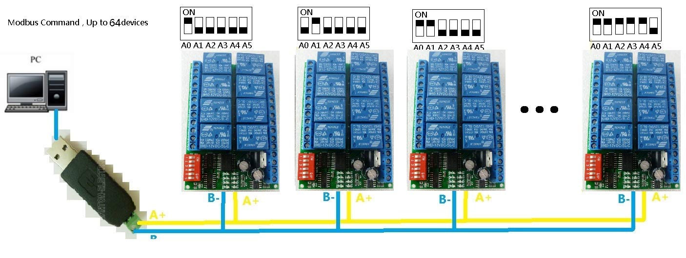
Figure 2: Modbus PC Connection Diagram. This diagram shows the connection of multiple RS485 relay boards to a personal computer (PC) via a USB to RS485 converter. Similar to the PLC setup, the A+ and B- lines are connected in parallel to enable Modbus communication from the PC.
5.3. Load Wiring
Each relay has normally open (NO), normally closed (NC), and common (COM) terminals. Wire your electrical loads to the appropriate relay terminals based on your application requirements. Ensure the load current and voltage do not exceed the relay's maximum ratings.

Figure 3: Relay Board Wiring Diagram (AC/DC Load). This image displays the wiring for connecting various loads to the 8-channel relay board. It shows connections for both AC (1-110V or 85-265V) and DC (12V) loads, along with the DC 12V power input and RS485 A+ and B- communication lines. The DIP switch for addressing is also visible.

Figure 4: Relay Board Wiring Diagram (DC Load). Similar to Figure 3, this diagram focuses on connecting DC loads to the relay board. It clearly labels the DC 12V power input, RS485 communication lines, and the load connections for each of the 8 relays.
5.4. DIP Switch Configuration
The relay board features a DIP switch (labeled 1-6 and A0-A5 in the diagrams) used for setting the device address in Modbus mode. Refer to the specific product documentation or the manufacturer's website for detailed instructions on configuring the DIP switches for unique device addresses when using multiple modules.
6. Operating Modes
The relay board supports two main operating modes: AT Command and Modbus RTU Command.
6.1. AT Command Mode
In AT command mode, the module responds to specific AT commands sent via the serial port. This mode allows for direct control and configuration. The maximum delay for relay operations in AT command mode is 9999 seconds.
6.2. Modbus RTU Command Mode
The Modbus RTU command mode is ideal for integration into industrial control systems (PLCs) or software applications. It supports up to 64 devices in parallel on a single RS485 bus. The maximum delay for relay operations in Modbus command mode is 255 seconds.
Control Methods:
- Serial HyperTerminal: Can be used for sending Modbus RTU commands (HEX format). Manual addition of CRC (Cyclic Redundancy Check) is required.
- Modbus Poll Software: This software automatically adds the CRC to Modbus commands, simplifying testing and control.
- PLC or MCU Process Control: Integrate the module into your PLC or Microcontroller Unit (MCU) programming for automated control.
Available Commands:
The module supports the following 6 commands for relay control:
- Open: Activates a specified relay.
- Close: Deactivates a specified relay.
- Momentary: Activates a relay for a brief period and then deactivates it.
- Self-locking: Toggles the state of a relay with each command.
- Interlock: Ensures that only one relay in a group can be active at a time.
- Delay: Activates or deactivates a relay after a specified time delay.
Specific Modbus function codes and register addresses for these commands should be referenced in the detailed Modbus protocol documentation provided by the manufacturer.

Figure 5: Modbus Poll Software Interface. This screenshot shows the user interface of Modbus Poll software, a common tool for testing and controlling Modbus RTU devices. It displays connection status and data registers.

Figure 6: Serial Port Tester Software Interface. This image displays a generic serial port tester application, which can be used to send and receive serial data, including AT commands or raw Modbus RTU commands (with manual CRC calculation).
7. Troubleshooting
- No Power: Check the 12V DC power supply connection and ensure it is within the 9-13V range. Verify polarity.
- No Communication:
- Verify RS485 A+ and B- connections are correct and secure.
- Ensure the RS485 converter (if used) is properly installed and its drivers are functioning.
- Check the baud rate, data bits, parity, and stop bits settings in your communication software (e.g., Modbus Poll, HyperTerminal) match the module's default or configured settings.
- Confirm the device address set by the DIP switches matches the address used in your commands.
- Relay Not Activating:
- Check the load wiring for continuity and correct connection to NO/NC/COM terminals.
- Ensure the load current and voltage do not exceed the relay's maximum ratings.
- Verify that the correct command is being sent to the specific relay channel.
- Intermittent Operation: Check for loose connections, power supply fluctuations, or electromagnetic interference. Use shielded cables for RS485 if interference is suspected.
8. Maintenance
The eletechsup RS485 Relay Board is designed for reliable operation with minimal maintenance. Follow these guidelines:
- Keep the module clean and free from dust and debris. Use a soft, dry cloth for cleaning.
- Periodically inspect all wiring connections for tightness and signs of wear or corrosion.
- Ensure adequate ventilation around the module, especially if operating in high-temperature environments.
- Avoid exposing the module to harsh chemicals or solvents.
9. Warranty and Support
For warranty information, technical support, or further inquiries, please contact eletechsup customer service or refer to the official product page where you purchased the item. Keep your purchase receipt for warranty claims.


