1. Introduction
This manual provides detailed instructions for the installation, setup, operation, and maintenance of the Dayton Time Delay Relay, Model 31EE10. This multifunction relay is designed for precise timing control in various electrical applications, featuring a wide time range and multiple operating functions.
2. Product Overview
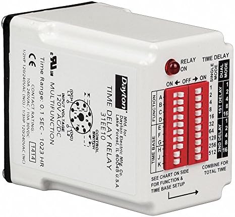
Figure 1: Dayton Time Delay Relay, Model 31EE10. This image displays the Dayton Time Delay Relay, model 31EE10. The front panel features a red LED indicator for relay status, two banks of red DIP switches for function and time base settings, and a label detailing input voltage (120V AC/DC), contact rating (10A 240VAC/30VDC), and time range (0.1 sec - 1023 hr). A diagram for the 8-pin control switch is also visible. The side of the relay provides instructions to 'SEE CHART ON SIDE FOR FUNCTION & TIME BASE SETUP' and 'COMBINE FOR TOTAL TIME'.
The Dayton 31EE10 is a versatile time delay relay offering 16 operating functions and a broad time range from 50 milliseconds to 10,230 hours. It operates on 120VAC/DC and features a 10A SPDT contact form. The unit is designed for plug-in mounting and includes user-configurable DIP switches for function and time base selection.
3. Specifications
| Specification | Value |
|---|---|
| Model Number | 31EE10 |
| Manufacturer | Dayton |
| Input Voltage | 120VAC/DC |
| Coil Voltage | 120 Volts |
| Contact Form | SPDT (Single Pole Double Throw) |
| Contact Type | Normally Open |
| Contact Amp Rating (Resistive) | 10 Amps |
| Contact Material | Silver Tin Oxide |
| Minimum Time Setting | 50 msec |
| Maximum Time Setting | 10,230 hr |
| Number of Functions | 16 |
| Wattage | 2 watts |
| Operation Mode | Automatic |
| Mounting Type | Plug In Mount |
| Plug Profile | Plug In Mount |
| Product Dimensions | 10.16 x 5.08 x 2.54 cm (4 x 2 x 1 inches) |
| Weight | 454 g |
| Certifications | CE |
| Batteries Required? | No |
4. Setup
Proper setup of the Dayton 31EE10 relay involves configuring the desired function and time base using the integrated DIP switches. Always ensure power is disconnected before making any adjustments.
- Mounting: Insert the relay into a compatible 8-pin socket. Ensure a secure connection.
- Function Selection: Locate the DIP switches labeled 'FUNCTION' on the front panel. Refer to the chart provided on the side of the physical product for the specific switch settings corresponding to the desired operating function (e.g., A, B, C, etc.). Adjust the switches accordingly.
- Time Base Setup: Locate the DIP switches labeled 'TIME BASE'. These switches are used to set the delay duration. The chart on the side of the product will indicate how to combine these settings for the '1st Delay' and '2nd Delay' (if applicable for the chosen function) to achieve the 'TOTAL TIME'. Each switch typically represents a binary value (e.g., 1, 2, 4, 8, 16, 32, 64, 128, 256, 512).
- Wiring: Connect the input voltage (120VAC/DC) and control switch wiring to the appropriate pins of the 8-pin socket as indicated by the wiring diagram on the relay. Ensure all connections adhere to local electrical codes and safety standards.
- Contact Wiring: Wire the load to the SPDT contacts (Normally Open/Normally Closed) according to your application requirements and the contact rating of 10A 240VAC/30VDC.
Note: Always consult the detailed function and time base charts printed on the physical relay for precise configuration instructions.
5. Operating Instructions
Once the relay is properly installed and configured, follow these steps for operation:
- Apply Power: Connect the power supply to the relay. The relay's red LED indicator will illuminate to show its status (ON/OFF).
- Monitor Relay Status: The LED indicator provides visual feedback on the relay's state.
- Time Delay Modes: Depending on the selected function, the relay will operate in either 'SINGLE MODE' or 'DUAL MODE'.
- Function Execution: The relay will execute the programmed time delay function based on the DIP switch settings. For functions requiring multiple delays, the '1st Delay' and '2nd Delay' settings will combine to determine the 'TOTAL TIME'.
- Automatic Operation: The relay operates automatically once power is applied and the conditions for the selected function are met.
6. Maintenance
The Dayton 31EE10 Time Delay Relay is designed for reliable, long-term operation with minimal maintenance. Adhere to the following guidelines:
- Regular Inspection: Periodically inspect the relay and its connections for any signs of damage, loose wiring, or corrosion.
- Cleaning: Keep the relay clean and free from dust and debris. Use a soft, dry cloth for cleaning. Do not use liquid cleaners or solvents.
- Environmental Conditions: Ensure the relay operates within its specified environmental conditions (temperature, humidity) to prevent premature failure.
- Power Disconnection: Always disconnect power to the relay before performing any inspection or cleaning.
7. Troubleshooting
If the Dayton 31EE10 relay does not operate as expected, consider the following troubleshooting steps:
- No Power/No LED:
- Verify that the input voltage (120VAC/DC) is correctly applied to the relay pins.
- Check for blown fuses or tripped circuit breakers in the power supply circuit.
- Ensure the relay is securely seated in its socket.
- Incorrect Timing:
- Re-check the 'TIME BASE' DIP switch settings against the product's time chart.
- Confirm that the 'FUNCTION' DIP switches are set for the desired operating mode.
- Ensure that the 'COMBINE FOR TOTAL TIME' calculation is correctly applied if using dual delay modes.
- Relay Not Actuating:
- Verify that the control input is correctly wired and receiving the expected signal.
- Check the load wiring for continuity and proper connection to the SPDT contacts.
- Ensure the selected function is appropriate for the desired trigger and output action.
- Intermittent Operation:
- Inspect all wiring connections for looseness or damage.
- Check for stable input voltage.
- Ensure the operating environment is free from excessive vibration or extreme temperatures.
If issues persist after performing these checks, contact qualified technical support.
8. Warranty and Support
Dayton products are manufactured to high-quality standards. For specific warranty information, please refer to the documentation provided with your purchase or contact Dayton customer service. Technical support is available to assist with any questions regarding the installation, operation, or troubleshooting of your 31EE10 Time Delay Relay.


