
1. Introduction
The Lomvum T28B Auto-Ranging Digital Multimeter is a versatile and high-precision electrical testing instrument. It is designed for accurate measurement of various electrical parameters, making it suitable for household, automotive, and general electrical applications. This manual provides detailed instructions for the safe and effective use of your multimeter.
The T28B features a 6000-count LCD backlight display, True RMS measurement capability, and functions including AC/DC Voltage, Current, Resistance, Continuity, Diode, Temperature, and Capacitance testing.
2. Package Contents
Upon opening the package, verify that all the following items are present and in good condition:
- Lomvum Auto-Ranging Digital Multimeter (T28B)
- 4 x 1.5V AAA Batteries
- English User's Manual
- Test Leads (Red and Black)
- K-type Thermocouple
- Alligator Clips (for test leads)
- 2 x Spare Fuses

Image 2.1: Lomvum T28B Digital Multimeter with test leads, K-type thermocouple, alligator clips, and AAA batteries.
3. Key Features
- Large Measurement Range: Measures DC Voltage up to 1000V, AC Voltage up to 750V, AC/DC Current up to 10A, Resistance up to 60MΩ, and Capacitance up to 100mF.
- 6000 Counts Display: Provides high resolution for precise readings.
- Auto-Ranging Function: Automatically selects the correct measurement range, simplifying operation.
- True RMS: Ensures accurate readings for non-sinusoidal AC waveforms.
- Backlit LCD Display: A 2.7-inch large display with backlight for clear visibility in dimly lit environments.
- Built-in Flashlight: Enhances visibility in dark work areas.
- Non-Contact Voltage (NCV) Detection: Detects AC voltage without direct contact, indicating presence with LED lights and an audible beeper.
- Data Hold Function: Freezes the displayed reading for convenient recording.
- Integrated Kickstand: Allows for hands-free operation.
- Safety Compliance: Meets 600V CAT IV and 1000V CAT III safety standards.
4. Safety Information
Always adhere to safety precautions when using the multimeter to prevent electric shock or damage to the instrument. Read and understand all safety instructions before operation.
- Do not exceed the maximum input values specified for each function.
- Use caution when working with voltages above 30V AC RMS, 42V peak, or 60V DC. These voltages pose a shock hazard.
- Ensure the test leads are properly connected to the correct input terminals for the selected measurement function.
- Inspect test leads for damaged insulation or exposed metal before use. Replace if damaged.
- Do not operate the multimeter if it appears damaged or if the case is open.
- Remove test leads from the circuit before changing functions or ranges.
- Replace batteries immediately when the low battery indicator appears to ensure accurate readings.
- Always disconnect power to the circuit and discharge all high-voltage capacitors before performing resistance, continuity, or diode tests.
5. Product Overview
5.1. Physical Layout and Dimensions
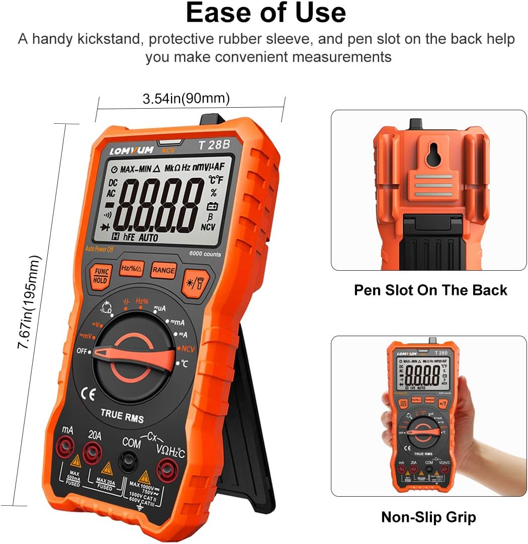
Image 5.1: Front view of the Lomvum T28B Multimeter showing dimensions (7.67 inches height, 3.54 inches width), integrated kickstand, and pen slot on the back.
The Lomvum T28B is designed with a protective rubber sleeve for durability and a non-slip grip. It features a handy kickstand for convenient hands-free measurements and a pen slot on the back for storing test leads.
5.2. Display and Controls

Image 5.2: Close-up of the 3.0-inch backlit LCD screen displaying measurement units and function symbols including AC/DC Voltage (V), AC/DC Current (A), Frequency (Hz), Resistance (Ω), Temperature (°C/°F), Duty Cycle (%), Capacitance, Diodes, Continuity, True RMS (TRMS), Non-Contact Voltage (NCV), and Auto Ranging (AUTO).
The multimeter features a large, backlit LCD screen for clear readings. The rotary dial is used to select the desired measurement function. Buttons on the front panel provide additional controls:
- FUNC/HOLD: Press to cycle through sub-functions (e.g., AC/DC for voltage/current, Diode/Continuity) or to activate/deactivate Data Hold.
- Hz/%/RANGE: Press to switch between Frequency and Duty Cycle measurement, or to manually select measurement range (when not in auto-ranging mode).
- ★/🔆: Activates/deactivates the backlight and flashlight simultaneously.
6. Setup
6.1. Battery Installation
The Lomvum T28B requires four 1.5V AAA batteries for operation. The battery compartment is located on the back of the unit.
- Ensure the multimeter is turned OFF.
- Locate the battery compartment cover on the back of the multimeter.
- Use a small Phillips head screwdriver to loosen the screw securing the battery cover.
- Remove the cover.
- Insert the four AAA batteries, observing the correct polarity (+ and -) as indicated inside the compartment.
- Replace the battery cover and tighten the screw.
6.2. Connecting Test Leads
Always connect the test leads correctly to the multimeter terminals before making any measurements.
- Insert the black test lead into the COM (Common) terminal.
- For most voltage, resistance, capacitance, diode, continuity, frequency, and temperature measurements, insert the red test lead into the VΩHzC terminal.
- For current measurements up to 600mA, insert the red test lead into the mA terminal.
- For current measurements up to 10A, insert the red test lead into the 20A terminal.
7. Operating Instructions
7.1. General Operation
To power on the multimeter, rotate the central dial from the OFF position to any desired measurement function. The multimeter features an auto-power-off function to conserve battery life if left idle.

Image 7.1: The Lomvum T28B Multimeter in use, measuring voltage on an automotive battery.
7.2. Measuring AC/DC Voltage (V)
- Set the rotary dial to the V position. The multimeter will automatically detect AC or DC voltage. If needed, press the FUNC/HOLD button to manually switch between AC and DC.
- Connect the black test lead to the COM terminal and the red test lead to the VΩHzC terminal.
- Connect the test probes in parallel across the circuit or component to be measured.
- Read the voltage value on the display.
7.3. Measuring AC/DC Current (A)
- Set the rotary dial to the mA or 20A position, depending on the expected current.
- Connect the black test lead to the COM terminal. Connect the red test lead to the mA terminal for currents up to 600mA, or to the 20A terminal for currents up to 10A.
- Disconnect power to the circuit. Open the circuit and connect the multimeter in series with the circuit or component to be measured.
- Apply power to the circuit and read the current value on the display.
7.4. Measuring Resistance (Ω)
- Set the rotary dial to the Ω position.
- Connect the black test lead to the COM terminal and the red test lead to the VΩHzC terminal.
- Ensure the circuit or component is de-energized and all capacitors are discharged.
- Connect the test probes across the component to be measured.
- Read the resistance value on the display.
7.5. Measuring Capacitance (C)
- Set the rotary dial to the C position.
- Connect the black test lead to the COM terminal and the red test lead to the VΩHzC terminal.
- Ensure the capacitor is fully discharged before testing.
- Connect the test probes across the capacitor terminals.
- Read the capacitance value on the display.
7.6. Diode Test (→|•))
- Set the rotary dial to the →|•)) position. Press FUNC/HOLD if necessary to select the diode test function.
- Connect the black test lead to the COM terminal and the red test lead to the VΩHzC terminal.
- Ensure the diode is disconnected from the circuit.
- Connect the red probe to the anode and the black probe to the cathode of the diode. A forward voltage drop will be displayed.
- Reverse the probes. The display should show 'OL' (Open Loop) for a good diode.
7.7. Continuity Test (•))
- Set the rotary dial to the →|•)) position. Press FUNC/HOLD if necessary to select the continuity test function.
- Connect the black test lead to the COM terminal and the red test lead to the VΩHzC terminal.
- Ensure the circuit or component is de-energized.
- Connect the test probes across the circuit or component.
- If continuity exists (resistance below approximately 50Ω), the multimeter will emit an audible beep.
7.8. Non-Contact Voltage (NCV) Detection
- Set the rotary dial to the NCV position.
- Move the top end of the multimeter (where the NCV sensor is located) close to the conductor or outlet you wish to test.
- If AC voltage is detected, the visible LED lights will illuminate (low, medium, high intensity) and the beeper will sound at varying frequencies, indicating the signal strength.

Image 7.2: The Lomvum T28B Multimeter performing a Non-Contact Voltage (NCV) test near a power strip to detect live wires.
7.9. Temperature Measurement (°C/°F)
- Set the rotary dial to the °C/°F position.
- Connect the K-type thermocouple to the multimeter. The red plug connects to the VΩHzC terminal and the black plug connects to the COM terminal.
- Place the tip of the thermocouple on or near the object whose temperature you wish to measure.
- Read the temperature value on the display. Press FUNC/HOLD to switch between Celsius and Fahrenheit.

Image 7.3: The Lomvum T28B Multimeter measuring the temperature of water using the included K-type thermocouple.
7.10. Frequency (Hz) and Duty Cycle (%) Measurement
- Set the rotary dial to the Hz/% position.
- Connect the black test lead to the COM terminal and the red test lead to the VΩHzC terminal.
- Connect the test probes across the signal source.
- Read the frequency (Hz) or duty cycle (%) value on the display. Press the Hz/%/RANGE button to toggle between frequency and duty cycle.
8. Maintenance
8.1. Cleaning
To clean the multimeter, wipe the case with a damp cloth and a mild detergent. Do not use abrasives or solvents. Ensure the multimeter is completely dry before use.
8.2. Battery Replacement
When the low battery indicator appears on the display, replace the batteries promptly to ensure accurate measurements. Refer to Section 6.1 for battery installation instructions.
8.3. Fuse Replacement
If the multimeter fails to measure current, the fuse may be blown. The Lomvum T28B uses ceramic fuses. Two spare fuses are included in the package.
- Ensure the multimeter is turned OFF and all test leads are disconnected.
- Carefully pry off the outer rubber protective cover from the bottom of the multimeter.
- Remove the four screws that secure the back cover of the meter.
- Gently lift the back cover to expose the internal circuit board. The fuses are typically located at the bottom of the circuit board.
- Identify the blown fuse (often visually indicated by a broken filament or discolored glass). You may use another multimeter to test continuity across the fuses if unsure.
- Carefully remove the blown fuse and replace it with a new fuse of the same type and rating. (Refer to specifications for fuse ratings).
- Reassemble the multimeter by replacing the back cover, tightening the screws, and reattaching the rubber protective cover.
8.4. Storage
If the multimeter is not used for an extended period, remove the batteries to prevent leakage and damage to the instrument. Store the multimeter in a cool, dry place away from direct sunlight and extreme temperatures.
9. Troubleshooting
This section addresses common issues encountered during multimeter operation.
| Problem | Possible Cause | Solution |
|---|---|---|
| Multimeter does not power on. | Dead or incorrectly installed batteries. | Check battery polarity; replace batteries. |
| No reading or 'OL' (Overload) displayed. | Incorrect range selected (if not auto-ranging); open circuit; input limits exceeded. | Ensure correct function/range; check circuit continuity; verify input is within limits. |
| Inaccurate readings. | Low battery; damaged test leads; external interference. | Replace batteries; inspect/replace test leads; move away from strong electromagnetic fields. |
| Current measurement fails. | Blown fuse; incorrect terminal connection. | Check/replace fuse (refer to Section 8.3); ensure red lead is in mA or 20A terminal. |
| NCV function is inconsistent. | Weak signal; environmental factors. | Ensure close proximity to live conductor; NCV is for indication, not precise measurement. |
| Backlight/Flashlight stays on. | Normal operation for a set duration; no separate control. | The backlight and flashlight operate simultaneously and will turn off automatically after a period of inactivity or when the meter is turned off. |
10. Specifications
| Parameter | Value |
|---|---|
| Display | 6000 Counts, Backlit LCD |
| DC Voltage Range | Up to 1000V |
| AC Voltage Range | Up to 750V |
| DC Current Range | Up to 10A |
| AC Current Range | Up to 10A |
| Resistance Range | Up to 60MΩ |
| Capacitance Range | Up to 100mF |
| Temperature Range | -20°C to 1000°C (-4°F to 1832°F) |
| Frequency Range | Yes (Hz) |
| Duty Cycle | Yes (%) |
| Diode Test | Yes |
| Continuity Test | Yes (with audible beep) |
| NCV (Non-Contact Voltage) | Yes |
| True RMS | Yes |
| Power Source | 4 x 1.5V AAA Batteries |
| Safety Rating | 600V CAT IV, 1000V CAT III |
| Item Weight | 380 Grams (13.4 ounces) |
| Dimensions | Approx. 7.67 x 3.54 x 2.44 inches (195 x 90 x 62 mm) |
| Fuse Ratings | F600mA/250V (mA input), F10A/250V (10A input) - *Note: Review mentions 250V rating, but safety rating is higher. Always use specified fuses.* |
11. Warranty and Customer Support
11.1. Warranty Information
The Lomvum Digital Multimeter T28B comes with a 24-Month Warranty from the date of purchase. This warranty covers defects in materials and workmanship under normal use. It does not cover damage resulting from misuse, unauthorized modification, accident, or neglect.
11.2. Customer Support
For technical assistance, warranty claims, or any inquiries regarding your Lomvum T28B multimeter, please contact Lomvum customer support. You can find more information and contact details on the official Lomvum store page: