
Introduction
This manual provides comprehensive instructions for the installation, operation, and maintenance of the Faria 8'' - 16'' Fuel Sender, Model 91001. This precision instrument is engineered to accurately measure fuel levels in tanks with depths ranging from 8 to 16 inches, transmitting reliable data to your compatible fuel gauge. Proper installation and care will ensure optimal performance and longevity of the unit.
Product Overview
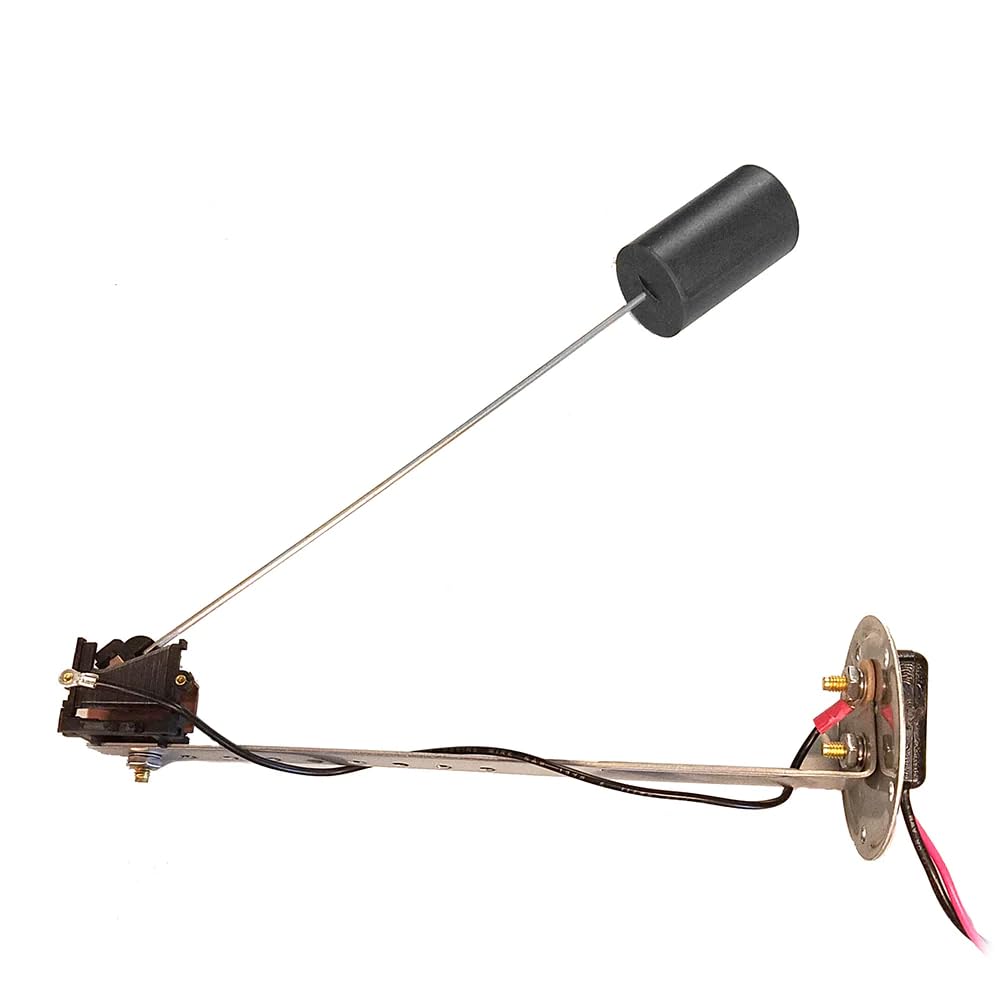
Figure 1: The Faria 8'' - 16'' Fuel Sender. This image displays the complete fuel sender unit, featuring the main body with electrical connections, the adjustable metal arm, and the cylindrical float at the end of the arm. The wiring for connection to a fuel gauge is also visible.
The Faria Fuel Sender is a robust and adjustable unit designed for various fuel tank applications. It utilizes a float mechanism to detect the fuel level, converting it into an electrical signal that can be read by a compatible fuel gauge. Its adjustable arm allows for customization to fit tanks between 8 and 16 inches deep, making it versatile for different vessel or vehicle requirements.
Setup and Installation
Safety Precautions
- Ensure the fuel tank is empty or at a very low level before beginning installation.
- Disconnect all power to the fuel system and battery before working on electrical components.
- Work in a well-ventilated area to avoid accumulation of fuel vapors.
- Have a fire extinguisher readily available.
Installation Steps
- Prepare the Mounting Location: Identify a suitable mounting location on the top of the fuel tank that allows the float arm to move freely from empty to full without obstruction. The location should also allow for easy access for wiring.
- Adjust Sender Length: The sender is adjustable for tank depths between 8 and 16 inches. Loosen the adjustment screw on the sender arm and slide the float to the desired length. Ensure the float will not bottom out or hit the top of the tank when fully extended or retracted. Tighten the adjustment screw securely.
- Mount the Sender: If a pre-existing mounting flange is available, align the sender's flange with the tank opening. Use appropriate gasket material (not included) to ensure a fuel-tight seal. Secure the sender using the provided screws or bolts. If no opening exists, a new opening must be cut and a mounting plate installed, following industry standards for fuel tank modifications.
- Wire Connections:
- Connect the sender's signal wire (typically a single wire) to the 'S' (Sender) terminal on your fuel gauge.
- Connect the sender's ground wire to a reliable chassis or battery ground. Ensure all connections are clean and secure.
- Test Connections: Before fully sealing the tank, perform a preliminary test by adding a small amount of fuel and observing the gauge response. The gauge should show an increase in fuel level.
Operating Instructions
The Faria Fuel Sender operates automatically once installed and wired correctly. It continuously monitors the fuel level in the tank and transmits this information to the connected fuel gauge.
Initial Operation and Calibration
- After installation, ensure all electrical connections are secure and the fuel tank is properly sealed.
- Turn on the vehicle's or vessel's ignition to power the fuel gauge.
- Fill the fuel tank completely. The fuel gauge should indicate a full tank.
- Operate the vehicle/vessel and observe the fuel gauge as fuel is consumed. The gauge should provide a smooth and consistent reading of the decreasing fuel level.
- If the gauge does not respond or provides erratic readings, refer to the Troubleshooting section.
Maintenance
The Faria Fuel Sender is designed for minimal maintenance. However, periodic inspection can help ensure its continued accuracy and prevent potential issues.
- Annual Inspection: Annually, or during routine vehicle/vessel maintenance, inspect the sender's mounting flange for any signs of fuel leaks. Check the electrical connections for corrosion or looseness.
- Float Arm Movement: Ensure the float arm moves freely without obstruction. Debris or sludge in the tank could impede its movement.
- Cleaning: If the sender needs cleaning, use a soft cloth and a mild, non-abrasive cleaner. Avoid harsh chemicals that could damage the float material or electrical components. Ensure the tank is empty and well-ventilated before any internal cleaning.
- Wiring Integrity: Periodically check the wiring leading to and from the sender for fraying, cuts, or damage. Replace any damaged wiring immediately.
Troubleshooting
If you experience issues with your Faria Fuel Sender, consult the table below for common problems and their solutions.
| Problem | Possible Cause | Solution |
|---|---|---|
| Fuel gauge reads empty or full constantly. |
|
|
| Inaccurate or erratic fuel readings. |
|
|
| No reading on fuel gauge. |
|
|
Specifications
| Feature | Detail |
|---|---|
| Brand | Faria |
| Model Name | 91001 |
| Part Number | 91001 |
| Adjustable Length | 8 to 16 inches |
| Operation Mode | Automatic |
| Contact Type | Normally Open |
| Connector Type | Screw Terminals |
| Terminal Type | Screw |
| Item Dimensions (L x W x H) | 11 x 10 x 3 inches (approximate, as packaged) |
| Item Weight | 1.6 ounces |
| Contact Material | Copper |
| International Protection Rating | IP00 |
| Manufacturer | Faria Beede Instruments |
| UPC | 759266910010 |
Warranty and Support
This Faria product comes with a manufacturer's warranty. For specific details regarding the warranty period, coverage, and claims process, please refer to the warranty documentation included with your purchase or visit the official Faria website.
For technical support, troubleshooting assistance beyond this manual, or inquiries about replacement parts, please contact Faria customer service. Contact information can typically be found on the product packaging or the manufacturer's official website.
Please retain your proof of purchase for warranty claims.
