
1. Introduction
The CNCTOPBAOS V5 3D Touch Probe Edge Finder is a precision tool designed to enhance the accuracy and efficiency of CNC milling operations. This device facilitates quick centering, edge finding, center finding, and shape measurement by integrating with your CNC control system. Its robust design and high repeatability make it an essential component for precise workpiece positioning.

Image 1: CNCTOPBAOS V5 3D Touch Probe Edge Finder with included cable and wrench.
2. Product Features
- Function: The three-coordinate probe enables quick centering, edge finding, center finding, and shape measurement by connecting to the CNC system.
- Software Compatibility: Compatible with various control panels such as GRBL and Mach3.
- Repeatability Accuracy: Achieves 0.01 mm / 0.0004 inch accuracy, simplifying workpiece positioning during machining.
- Wiring: NPN-NO 3-wire configuration: Red (VCC / DC5-24V power), Yellow (IO / Signal Output), Black (GND / DCM).
- Indicator Light: Green light indicates power on, red light illuminates upon triggering.
- Probe Material: The shell is constructed from fine frosted black oxidized aluminum alloy with an anti-roll design.
- Stylus Material: The probe tip/stylus is machined from stainless steel, featuring a tungsten steel ball head for wear resistance.
- Concentricity: Factory fine-tuned to within 0.05 mm. Users may need to measure and adjust upon receipt. Ensure use of ER11 spring chucks of AAA or above accuracy to prevent concentricity issues.

Image 2: The probe features a waterproof design for enhanced durability.
3. Specifications
| Attribute | Value |
|---|---|
| Manufacturer | Changzhou Rattm Motor Co.,Ltd |
| Item Weight | 5.6 ounces |
| Package Dimensions | 5.71 x 4.33 x 3.43 inches |
| Item Model Number | V5 |
| Style | Style B |
| Material | 3D Touch Probe Edge Finder-NO |
| Power Source | DC |
| Item Package Quantity | 1 |
| Included Components | 1x 3D touch probe, 1x Stainless steel probe tip, 1x cable |
| Batteries Included? | No |
| Batteries Required? | No |
| Date First Available | September 9, 2022 |
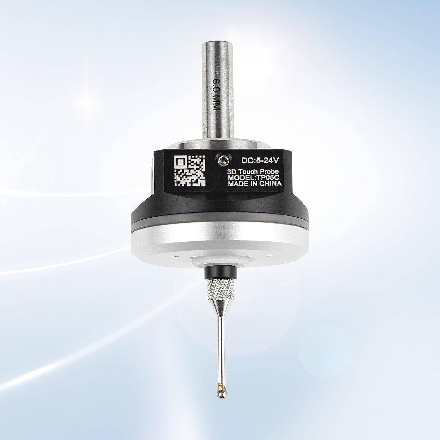
Image 3: Detailed dimensions of the V5 3D Touch Probe.
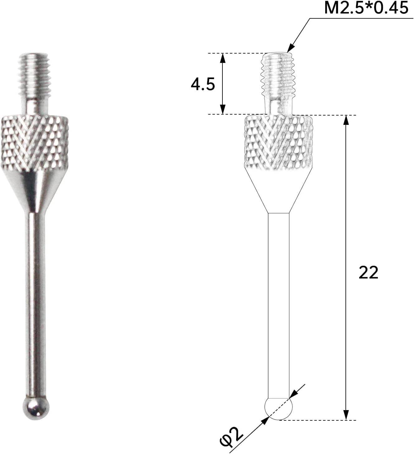
Image 4: Detailed dimensions of the probe tip.
4. Setup
4.1 Wiring Instructions
Connect the 3-wire NPN-NO cable to your CNC control board as follows:
- Red Wire: Connect to VCC (DC5-24V power supply).
- Yellow Wire: Connect to IO (Signal Output). The high level is the same as VCC.
- Black Wire: Connect to GND (Ground) or DCM.
The indicator light will be green when powered on. It will turn red when the probe is triggered, indicating a low IO level.

Image 5: Wiring diagram for the 3-wire NPN-NO probe.
4.2 Concentricity Adjustment
It is crucial to ensure the probe's concentricity for accurate measurements. Use a lever gauge for adjustment. The dial gauge shown in the video has too much elastic force to be used for this precise adjustment.
- Align the measuring needle with the center of the gauge ball head.
- Rotate the probe tip for one full circle to find the maximum and minimum values on the pointer.
- If the four squares are divided into A, B, C, D, adjust AC or BD first.
- Repeat the adjustment until the concentricity is approximately 0.01 mm.
For a visual guide on adjusting concentricity and removing the probe tip, please refer to the video below:
Video 1: Instructions on how to adjust the concentricity of the probe and remove the probe tip.
5. Operating Instructions
The 3D Touch Probe can be used for various measurement tasks on your CNC machine, including:
- Edge Finding: Precisely locate the edges of your workpiece.
- Centering: Find the exact center of holes or features.
- Shape Measurement: Measure complex geometries.
Ensure your CNC software (e.g., Mach3, GRBL) is configured to recognize and utilize the probe's signal output. Refer to your CNC software's documentation for specific probing routines and settings.

Image 6: The 3D Edge Finder in operation on a CNC machine.
5.1 Supported Software Interfaces
The probe is designed to work with common CNC control software. Below are examples of interfaces for Mach3 and GRBL:

Image 7: Examples of supported software interfaces: Probe Wizard for Mach3 and GrblGru for GRBL 1.1.
6. Maintenance
To ensure the longevity and accuracy of your 3D Touch Probe, follow these maintenance guidelines:
- Cleaning: Regularly clean the probe body and stylus tip with a soft, dry cloth. Avoid using harsh chemicals or abrasive materials.
- Storage: Store the probe in its protective case when not in use to prevent damage to the stylus tip.
- Concentricity Check: Periodically check and adjust the concentricity of the probe as described in Section 4.2.
- Stylus Replacement: If the stylus tip becomes damaged or worn, it can be replaced. Refer to the video in Section 4.2 for instructions on removing the tip.

Image 8: Parts Reference List for the 3D Touch Probe.
7. Troubleshooting
If you encounter issues with your 3D Touch Probe, consider the following:
- Inaccurate Readings: Check the probe's concentricity (refer to Section 4.2). Ensure your ER chuck has sufficient accuracy (AAA or above).
- No Signal/Indicator Light Issues: Verify all wiring connections are secure and correct (Red to VCC, Yellow to IO, Black to GND). Check the power supply voltage (DC5-24V).
- Software Recognition: Confirm that your CNC control software is properly configured to detect and interpret the probe's signal.
For further assistance, refer to the Q&A section below or contact customer support.
8. Frequently Asked Questions (Q&A)
- Q1: Do I need to turn on the spindle speed when using the probe?
- A1: No, absolutely not. The spindle speed should never be turned on when using the probe.
- Q2: How do I distinguish the three wires?
- A2: The red wire is VCC (power), the black wire is GND (ground), and the yellow wire is IO (signal output).
- Q3: Why is the concentricity different every time the probe is installed?
- A3: This often occurs because your ER chuck spring clip may not ensure 100% uprightness. Even if concentricity is adjusted to 0.01 mm, deviations can occur when the probe is removed and reinstalled. It is recommended to use a high-precision chuck (AAA accuracy or above, concentricity <=0.005 mm). After installing the chuck, use a high-precision gauge or tungsten steel rod to check the table's concentricity. Place the dial indicator approximately 50mm from the chuck, which is roughly the distance between the probe's ball head and the tool handle's root.
9. Warranty and Support
For technical support, warranty inquiries, or further assistance, please contact CNCTOPBAOS customer service through the retailer where the product was purchased. Please retain your proof of purchase for warranty claims.