1. Introduction
This manual provides essential information for the safe and efficient installation, operation, and maintenance of your Kohler RXT Series 200-Amp Automatic Transfer Switch (ATS). The ATS is a critical component of your generator system, designed to automatically manage the transfer of electrical power between your utility source and a standby generator.
Please read this manual thoroughly before attempting any installation, operation, or maintenance procedures. Retain this manual for future reference.
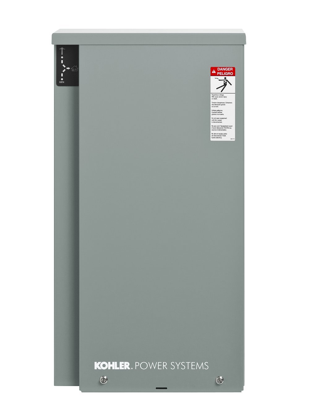
Image 1.1: Kohler RXT Series 200-Amp Automatic Transfer Switch. This image shows the exterior of the transfer switch unit, typically a gray, weather-resistant enclosure.
2. Safety Information
WARNING: Electrical shock hazard. Improper installation or maintenance can result in serious injury or death. This equipment must be installed and serviced by qualified electrical personnel only.
- Always disconnect all power sources (utility and generator) before servicing the transfer switch.
- Ensure proper grounding of the transfer switch enclosure.
- Follow all local and national electrical codes.
- Do not operate the transfer switch if any covers are removed or if the enclosure is damaged.
- Keep children and unauthorized personnel away from the equipment.
3. Product Overview and Key Features
The Kohler RXT Series Automatic Transfer Switch is designed to provide seamless power transfer for residential and light commercial applications. Its robust design ensures reliable operation in various environmental conditions.
Key Features:
- Kohler RDC2 or DC2 Controller Compatible: Designed for exclusive use with Kohler generator sets equipped with RDC2 or DC2 generator set/transfer switch controllers, allowing utility voltage display and interface board connection.
- 200 AMP Single Phase Model: Equipped with two single-phase poles and rated for 240-volts.
- Combined Interface/Load Management Board: Automatically manages up to six residential loads, including up to four customer-supplied, non-essential secondary loads and two independent HVAC loads.
- Versatile Indoor or Outdoor Installation: Features a corrosion-resistant, padlockable NEMA 3R aluminum enclosure that protects internal components from rain, snow, ice, debris, and dust.
- Safe Maintenance: Contactor is manually operable for maintenance purposes, enhancing safety during service.
4. Installation
Installation of the Kohler RXT Series Automatic Transfer Switch must be performed by a qualified electrician in accordance with all applicable electrical codes and standards.
4.1 Pre-Installation Checks
- Verify that the transfer switch model (RXT-JFNC-0200A-QS7) is compatible with your Kohler generator set (RDC2 or DC2 controller).
- Ensure the installation location is suitable for indoor or outdoor use, considering the NEMA 3R enclosure rating.
- Confirm that the utility and generator power sources are disconnected and locked out before beginning installation.
4.2 Mounting the Transfer Switch
- Select a sturdy, vertical surface for mounting, ensuring adequate clearance for wiring and maintenance.
- Use appropriate hardware to securely fasten the enclosure to the mounting surface.
4.3 Electrical Connections
Refer to the wiring diagrams provided with the transfer switch and generator for specific connection details. Key connections include:
- Utility Power Input
- Generator Power Input
- Load Output to Main Electrical Panel
- Control Wiring to Kohler RDC2 or DC2 Generator Controller
- Load Management Connections for secondary and HVAC loads.
All wiring must comply with the current rating of 200 Amps and operating voltage of 240 Volts.
5. Operation
The Kohler RXT Series ATS operates automatically, continuously monitoring the utility power supply.
5.1 Automatic Power Transfer
- Utility Power Present: Under normal conditions, the ATS connects your electrical loads to the utility power source.
- Utility Power Loss: When the ATS detects a loss of utility power, it signals the Kohler generator to start.
- Generator Power Transfer: Once the generator reaches proper operating voltage and frequency, the ATS automatically disconnects from the utility and connects your electrical loads to the generator power.
- Utility Power Restoration: When utility power is restored and stable, the ATS automatically transfers the electrical loads back to the utility source.
- Generator Shutdown: After a brief cool-down period, the ATS signals the generator to shut down.
5.2 Load Management
The integrated load management board allows the ATS to prioritize and manage up to six residential loads. This ensures that critical loads receive power during generator operation, even if the generator's capacity is limited. The system can manage up to four customer-supplied non-essential secondary loads and two independent HVAC loads.
6. Maintenance
Regular maintenance ensures the longevity and reliable operation of your automatic transfer switch. All maintenance should be performed by qualified personnel.
6.1 Scheduled Inspections
- Monthly: Visually inspect the exterior of the enclosure for any signs of damage, corrosion, or loose connections. Ensure the padlockable mechanism is secure.
- Annually: Have a qualified technician perform a thorough inspection of internal components, including wiring, contactors, and control boards. Check for dust accumulation and ensure all connections are tight.
6.2 Contactor Operation
The contactor is manually operable for maintenance purposes. This feature allows a technician to safely test the mechanical operation of the switch without live power, after ensuring all power sources are disconnected.
6.3 Cleaning
Keep the exterior of the enclosure clean. Use a soft, damp cloth to wipe away dust and debris. Do not use harsh chemicals or abrasive cleaners. Ensure the enclosure seals remain intact to maintain its NEMA 3R rating.
7. Troubleshooting
This section provides basic troubleshooting steps for common issues. For complex problems, contact a qualified service technician.
| Problem | Possible Cause | Solution |
|---|---|---|
| Generator does not start when utility power fails. |
|
|
| ATS does not transfer to generator power. |
|
|
| ATS does not transfer back to utility power. |
|
|
8. Specifications
The following specifications apply to the Kohler RXT Series 200-Amp Automatic Transfer Switch, Model RXT-JFNC-0200A-QS7:
| Feature | Specification |
|---|---|
| Model Number | RXT-JFNC-0200A-QS7 |
| Current Rating | 200 Amps |
| Operating Voltage | 240 Volts |
| Operation Mode | Automatic |
| Circuit Type | 2-way, Single Phase |
| Controller Compatibility | Kohler RDC2 or DC2 |
| Enclosure Rating | NEMA 3R (Indoor/Outdoor) |
| Enclosure Material | Aluminum |
| Load Management | Up to 6 residential loads (4 secondary, 2 HVAC) |
| Dimensions (L x W x H) | 7.1 x 13.2 x 24.5 inches |
| Item Weight | 17 pounds |
| UPC | 650531365453 |
9. Warranty and Support
The Kohler RXT Series Automatic Transfer Switch is backed by a comprehensive five-year/2000-hour limited warranty. This warranty covers defects in materials and workmanship under normal use and service.
For warranty claims, technical support, or to locate an authorized service dealer, please visit the official Kohler website or contact Kohler customer service. Kohler maintains a network of more than 10,000 dealers to provide expert assistance and service.
Online Support: www.kohler.com


